Assembly, Installation, Start Up User manual
■
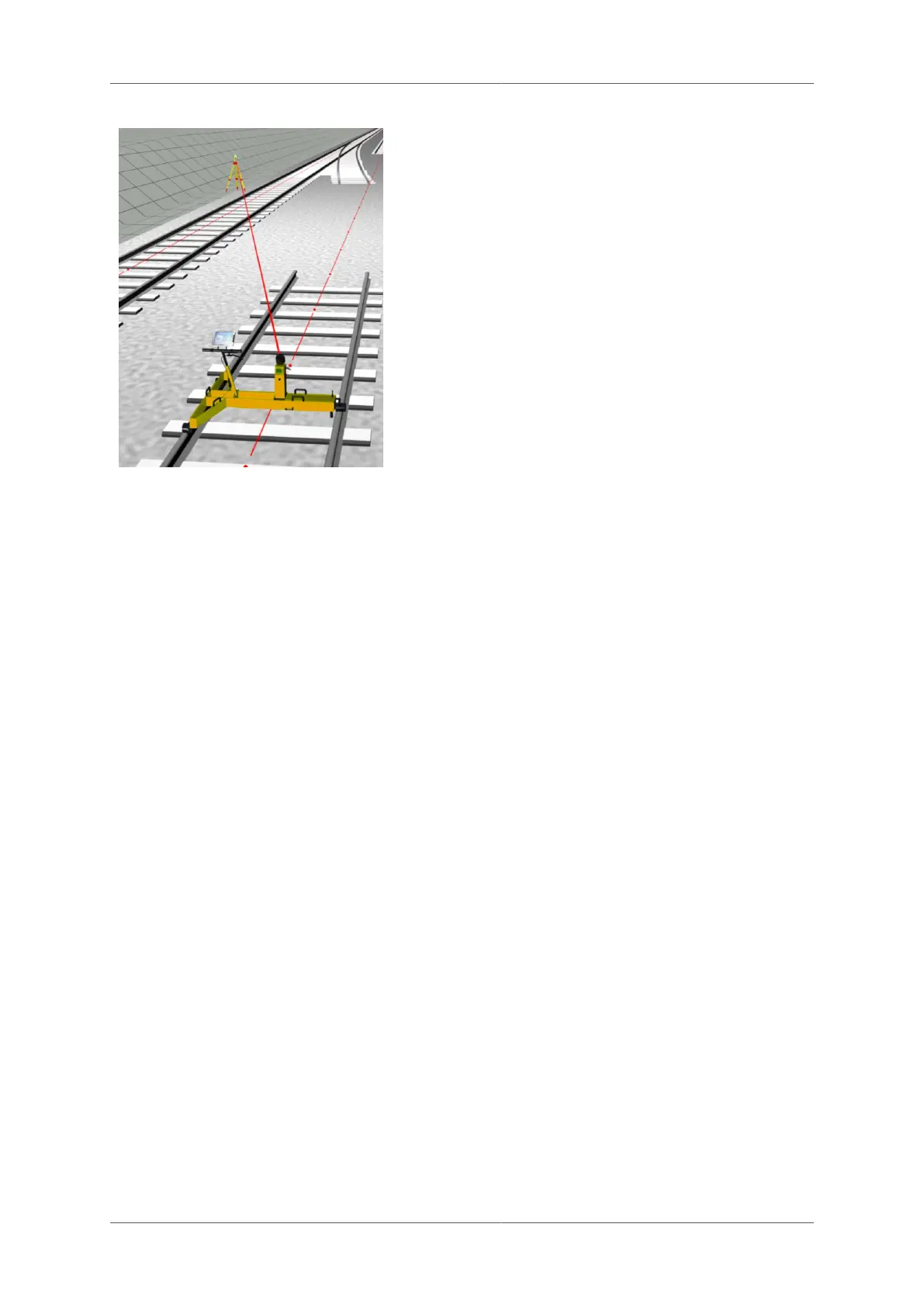
Set up the Leica total station at the desired
place. Connect the external battery and
radio modem using the y-cable.
■
Determine the position and orientation of
the total station with the installed programs
(orientation, resection or free station).
Make sure that you set the coordinates, the
tripod height and orientation correctly
■
Leica TCA2000 / Leica TPS1100: enable
GEOCOM mode
■
Leica TPS1200, Leica TS15/16, Leica
TS30, Leica TS50/60: A robotics license
has to be available to work with GRP
System FX.
■
Aim the total station in the direction of the
prism on the Profiler FX or on the prism
column.
4.7 Installation of GNSS system
4.7.1 Installation of GNSS antenna
Install the GNSS antenna pole on the TGS FX (see installation of prism column GPC 100).
Mount the GNSS antenna on the top of the antenna pole.
4.7.2 Cable connections
■
Leica GNSS1200/GS10
■
PWC GNSS1200/GS10 - Power cable TGS FX to GNSS1200/GS10 receiver: Connection
between power supply of the TGS FX and the power plug (PWR) of the Leica GNSS
Receiver
■
TAC GNSS1200/GS10 - Data adaptor cable TGS FX to GNSS1200/GS10 receiver:
Adaptor cable to connect the GNSS1200/GS10 receiver with the trolley TGS FX (used for
data communication)
■
Leica GS14/15/16/18
■
PWC GS14/15/16/18 - Adaptor / Power cable GS14/15/16/18 to TGS FX: Power and data
connection between TGS FX and Leica GNSS receiver.
For the other cable connections, which have to be established, please refer to the Leica GNSS
manual. Further instructions on how to set a GRP System FX up with GNSS can be found in
corresponding instruction manuals.
4.8 Installation of high-speed laser
The installation of the high-speed laser scanner is slightly different depending on the model
(see for list of supported models). The instructions below explain the differences.
4.8.1 Installation of the adaptor plate on the high-speed laser scanner
Page 48 of 114 © Amberg Technologies AG, 2023