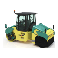
330 ARR1575
19 Appendices
19.2 Wiring diagram
Legend:
A1 ACEecon display
A2 ACEecon display
A3 ACEecon sensor
F11 Fuse, control unit, power supply
F12 Fuse, control unit, outputs
F13 Fuse, display unit, safety bar
F14 Fuse, hydraulic oil cooler
F21 Fuse, pull solenoid
F22 Fuse, fuel pump, alternator
F23 Fuse, working speed
F24 Fuse, ignition coil
F25 Fuse, second solenoid
G1 Alternator
G2 Battery
K1 Relay, ignition
K2 Relay, start lock
K3 Time relay
K4 Relay, pull solenoid
K5 Relay, working speed
K6 Relay, ignition coil
K7 Relay, hydraulic oil cooler
K11 Relay, solenoid exciter
M1 Starter
M2 Fuel pump
M3 Hydraulic oil cooler
N1 Machine control unit
N2 Display unit
N3 Infrared remote control
P1 Front infrared sensor
P2 Rear infrared sensor
R1 Ignition coil
S1 Switch, ignition switch
S21 Sensor, engine oil pressure
S22 Sensor, coolant temperature
S24 Sensor, safety bar
S25 Sensor, hydraulic oil temperature
Y1 Magnet, pull / holding solenoid
Y2 Magnet, working speed
Y3 Magnet, pump with adrive, forward
Y4 Magnet, pump with adrive, reverse
Y5 Valve, steering, left
Y6 Valve, steering, right
Y7 Valve, vibration with high amplitude
Y8 Valve, vibration with low amplitude
Y9 Valve, parking brake
Y11 Magnet, second solenoid
The texts are given only in the original language version or as a translation of the original into the English language version.