Do you have a question about the Anyview A6 and is the answer not in the manual?
| Brand | Anyview |
|---|---|
| Model | A6 |
| Category | Medical Equipment |
| Language | English |
Defines the monitor's purpose for monitoring, displaying, storing, and alarming physiological parameters.
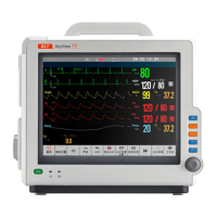
Details the front view of the AnyView A8, A6, A5, and A3 patient monitors.
Lists supported modules like EMS, MPS, IBP, Temp, SpO2, CO2, AG, ICG, C.O., CSM, BIS.
Provides a guide to common symbols used on the equipment and their meanings.
Covers warnings and cautions for safe operation, including electrical hazards and patient safety.
Provides installation precautions, environmental considerations, and notes on symbols related to safety.
Highlights key safety aspects like patient number, interference, liquid ingress, accuracy, and alarms.
Details conditions for safe operation, including sterilization, interference, and defibrillation shocks.
Guides users through unpacking, inspecting the monitor, and checking accessories for damage.
Covers inspecting the monitor and starting it up, including power and system checks.
Outlines steps to decide parameters, install modules, check settings, and begin patient monitoring.
Provides step-by-step instructions for safely shutting down the monitor.
Explains how to enter and resume monitoring from standby mode for temporary interruption.
Details connecting the monitor to a central monitoring system via electrical or Wi-Fi connection.
Describes the different operation modes: Monitor, Demo, Configuration, and Service.
Explains the standard screen layout, detailing areas like patient info, alarm status, and waveforms.
Describes how to use parameter and touch smartkeys for quick menu access and operations.
Guides on setting up and configuring measurement modules, including opening/closing parameters and changing labels.
Explains how to use a USB-interface mouse with the monitor, including hot plugging and basic operations.
Details the use of the software keyboard for data input in Chinese and English.
Explains how to use an SD memory card for data saving during power failures or power offs.
Covers adjusting screen brightness, volume settings, and system date/time configuration.
Covers setting screen layout, managing layouts, displaying alarm limits, parameter color, and sweep mode.
Explains how to set the screen layout by selecting Standard, Big Numerics, 7-lead, 12-lead, HI RES Trend, OxyCRG, NIBP Review, or Other Bed screens.
Classifies alarms into physiological, technical, and prompt messages.
Details the classification of physiological alarms into high, medium, and low levels.
Explains how alarms are indicated through tone, lamp, message, and flashing numeric.
Defines symbols for alarm sound status: off, suspended, or parameter alarm off.
Guides on setting the system's alarm volume level.
Covers setting alarm limits, alarm switch, and alarm level for individual parameters.
Explains how to silence audible alarms, noting that visual indicators remain active.
Details how to suspend all alarm indicators temporarily and how to cancel the pause.
Explains how to acknowledge active physiological and technical alarms, which shuts off audible and visual indicators.
Distinguishes between latching and non-latching alarms, noting exceptions like Arrhythmia alarm.
Provides steps to follow when an alarm occurs, emphasizing checking patient condition first.
Guides on admitting a patient, entering information like MRN, name, type, and settings.
Describes a faster method for admitting a patient when time or information is limited.
Explains how to edit patient information after a patient has been admitted.
Details the procedure for discharging a patient from the monitor.
Explains how to transfer patient data and settings using the EMS module for uninterrupted monitoring.
Explains the principle of ECG measurement, heart electrical activity, and dynamic curve formation.
Covers imperative safety guidelines for ECG electrodes, cables, and use during defibrillation.
Details skin preparation, electrode placement for 3, 5, and 12-lead ECG, and connecting the ECG cable.
Illustrates the ECG display screen, including waveform and parameter display areas.
Guides on setting ECG mode, QRS volume, primary lead, wave gain, wave speed, and filters.
Explains ST segment analysis, its display, switching on/off, and setting ST alarms.
Details arrhythmia analysis, switching it on/off, PVCs display, setting arrhythmia alarms, and relearning.
Covers QT/QTc interval monitoring, its display, switching on/off, and setting alarms.
Explains how the monitor measures thoracic impedance to calculate respiration rate (RR).
Provides safety warnings for Resp monitoring, including ECG cable use and patient motion.
Details connecting the ECG cable, placing Resp electrodes, optimizing lead placement, and understanding cardiac overlay.
Shows the Resp waveform and parameter display, including RR unit and alarm limit.
Guides on setting Resp parameters like lead, apnea alarm time, wave gain, and wave speed.
Explains the principle of SpO2 measurement using light spectra and volume tracing.
Covers safety warnings for SpO2 sensors, including MRI use, skin inspection, and interfering substances.
Details selecting, connecting, and applying the SpO2 sensor, with specific warnings.
Illustrates SpO2 parameter display, including signal intensity indicators and values for BLT and Masimo sensors.
Guides on setting SpO2 parameters like NIBP on same limb, QRS volume, wave speed, average time, and PR source.
Lists factors influencing SpO2 measurement accuracy, such as sensor application and lighting.
Explains how the monitor measures temperature using sensors, displaying up to eight channels and TD.
Provides safety warnings regarding disposable temp probes, calibration, and sensor handling.
Details selecting the correct temp probe, connecting it, applying it to the patient, selecting labels, and checking alarm settings.
Shows how temperature values and differences (TD) are displayed on the monitor.
Explains how to select parameters A and B for calculating the temperature difference (TD).
Explains the oscillometric method for measuring NIBP in adult, pediatric, and neonatal patients.
Covers safety warnings for NIBP monitoring, including patient category, sickle-cell disease, and limb restrictions.
Lists limitations for NIBP measurements, such as extreme heart rates and patient movement.
Describes the three NIBP measurement modes: Manual, Auto, and STAT.
Details preparing to measure NIBP, including patient category check, cuff selection, and connecting the cuff.
Illustrates the NIBP display screen, showing readings for Sys, Dia, Map, and time indicator.
Guides on setting NIBP parameters like unit, initial cuff inflation pressure, assisting venous puncture, and resetting.
States that NIBP maintenance and calibration are necessary every two years and require professional service.
Explains IBP measurement as direct BP measurement via pressure sensors and liquid coupling.
Covers safety warnings for IBP transducers, accessories, and use with HF surgical equipment.
Details plugging the IBP cable, connecting the transducer, filling the tube, selecting labels, and zeroing the transducer.
Illustrates IBP waveform and parameter displays, including labels, scales, and units.
Guides on setting IBP parameters like unit, display format, wave speed, wave scale, and high-resolution cursor.
Explains how the monitor calculates CPP by finding the difference between mean arterial and intracranial pressure.
Provides steps for zeroing the pressure transducer to ensure accurate readings, including pre-zeroing procedures.
States that pressure calibration ensures accurate measurements and should be performed by professional service personnel.
Explains CO2 measurement using infrared absorption technology and two methods: Mainstream and Sidestream/Microstream.
Details monitoring procedures for Mainstream and Sidestream CO2 modules, including attaching cables, adapters, and performing zeroing.
Shows the CO2 waveform and parameter display, including EtCO2, FiCO2, and airway respiration rate.
Guides on setting CO2 parameters like unit, apnea alarm time, expiring cycle, CO2 corrections, wave scale, and speed.
Explains the zeroing procedure for Mainstream and Microstream CO2 modules to obtain accurate readings.
States that calibration is done at the factory and may require user intervention for Sidestream modules under specific conditions.
Provides a warning about connecting the outlet to a scavenging system for anesthetic gases.
Covers safety information related to sensor cables, tubing, single-use kits, adapters, and module operation.
Explains AG module's purpose for measuring respiratory and anesthetic gases using infrared absorption.
Details monitoring procedures for Mainstream and Sidestream AG modules, including preparation and pre-use checks.
Shows the AG display with waveforms and numerics for CO2, O2, N2O, and AA, including MAC calculation.
Guides on setting AG parameters like type, wave scale, and wave speed.
Explains Minimum Alveolar Concentration (MAC) calculation based on end-tidal gas concentrations.
Covers safety information for Mainstream and Sidestream AG modules, including adapter reuse, secretions, and interference.
Details maintenance for Mainstream and Sidestream AG modules, focusing on zero reference calibration and preventive maintenance.
Discusses factors affecting performance, such as humidity, barometric pressure, interfering gases, and gas measurement units.
Introduces Impedance Cardiography (ICG) as a non-invasive method for measuring hemodynamic parameters.
Lists calculated parameters like HR, SV, SI, CO, TFC, SVR, QI, and DO2I with their formulas and reference ranges.
Provides safety warnings for ICG sensors, including MRI use, contact with conductive materials, and pacemaker compatibility.
Details skin preparation, connecting the ICG cable, placing sensors on the patient, and inputting patient information.
Lists ICG parameters and their full names, units, and values for hemodynamic monitoring.
Shows the ICG waveform and parameter displays, including primary and secondary parameters.
Guides on selecting secondary parameters A or B and setting wave speed for ICG.
Lists conditions or anomalies that may reduce ICG measurement accuracy, such as septic shock and patient height.
Explains Cardiac Output (C.O.) module using thermodilution method to measure blood flow.
Provides safety warnings for C.O. measurement, including accessory reuse, cable handling, and sterilization.
States there is no waveform display for C.O. measurement on the main interface, only parameter values.
Details the steps for measuring C.O., including inserting cables, connecting the catheter, and injecting solution.
Guides on setting C.O. parameters like measure mode, TI source, volume of injecta, catheter constant, weight, height, and alarm settings.
Lists restrictions for C.O. measurement, such as patient conditions like poor immune system or right heart valve disease.
Identifies factors influencing cardiac output measurement, including injectate temperature, volume, rate, and catheter position.
Introduces CSM for monitoring hypnotic brain state via EEG signals, calculating Cerebral State Index (CSI).
Provides safety warnings for CSM sensors, HF surgery, conductive parts, and module handling.
Details skin preparation, placing CSM sensors, connecting the patient cable, plugging the connection module, and starting the monitor.
Shows the CSM display with EEG waveform, trend graph, and parameters like CSI, BS%, and SQI.
Guides on setting CSM parameters such as alarm level, alarm print, SQI display, impedance display, EEG wave display, scale, and trend format.
Explains Bispectral Index (BIS) monitoring for assessing patient consciousness level during anesthesia via EEG signals.
Provides safety warnings for BIS sensors and connectors, HF surgery, and patient interface cable immobilization.
Details connecting BISx equipment, placing the sensor, connecting the patient interface cable, and ensuring proper sensor detection.
Shows the BIS display with EEG waveform, trend chart, and parameters like BIS, SQI, and EMG.
Guides on setting BIS parameters like smoothing rate, EEG filter, trend time, impedance check, wave scale, and wave select.
Explains how to set BIS alarm switch, alarm level, and alarm print options.
Details the front, side, and rear views of the EMS module, including indicators and connectors.
Describes the two EMS operation modes: Module Mode (connected to host) and Monitor Mode (independent).
Covers starting and shutting off the EMS, entering standby mode, and basic setup procedures.
Guides on EMS setup for language, date/time, AC frequency, system information, and Wi-Fi connection.
Describes the monitor's touch screen capabilities and different screen layouts like Standard and Custom.
Details measurement procedures and settings for ECG, Resp, PR, SpO2, Temp, NIBP, IBP, C.O., CSM, and BIS.
Explains how to freeze the waveform on the screen for careful survey of patient condition.
Details methods for browsing frozen waveforms using navigation controls for careful survey.
Explains how to release the frozen waveform condition using smartkey or button.
Guides on reviewing graphic trends, selecting parameters, setting intervals, and browsing trends.
Explains how to review tabular trends, select parameters, set intervals, and browse trends.
Details how to enter the NIBP review window and browse measurement results.
Explains how to review stored parameter values and waveforms at the time of an alarm event.
Describes how to review holographic waveforms, requiring SD card configuration, and storing waveforms.
Explains drug concentration calculation for physicians, including steps, units, and titration table.
Details hemodynamic calculation steps, inputting parameters for monitoring and calculation.
Explains Nephridium calculation steps, inputting parameters, and output parameters.
Covers ventilation calculation steps, inputting parameters, and output parameters.
Details oxygenation calculation steps, inputting parameters, and output parameters.
Explains ambulatory blood pressure monitoring technology and NIBP analysis steps.
Covers Heart Rate Variability analysis, including R-R histograms, scatter plots, and trend graphs.
Explains the Nurse Call function, connecting to the hospital system, and valid conditions for its operation.
Details the auxiliary output port for analog signal output to equipment like oscillographs.
Describes the thermal recorder, its indicator lamps, paper out port, and door.
Lists the types of records that can be divided according to trigger modes: real-time, circular, alarm, and manual.
Guides on setting the recorder for waveform selection, record speed, periodic recording interval, and alarm record.
Explains how to start and stop recording manually or automatically through periodic or alarm triggers.
Provides step-by-step instructions for installing recording paper into the recorder.
Details how to clear jammed paper from the recording meter.
Explains how to clean the recorder, including precautions for printing head and static discharge.
Explains the function of the rechargeable battery for continuous work after AC power failure.
Provides step-by-step instructions for installing or charging batteries in the monitor.
Guides on optimizing battery performance through initial optimizing cycles and regular conditioning.
Explains how to check battery performance by monitoring operating time after charging and discharging cycles.
Covers proper disposal of damaged or depleted batteries according to local regulations and safety warnings.
Details equipment maintenance procedures, including seasonal safety checks and electrical safety tests.
Provides rules for keeping equipment clean, including dilution instructions, avoiding immersion, and using appropriate materials.
Explains how to clean the monitor using common detergents and non-corrosive disinfectants.
Refers to Chapter 26.2 for maintenance and cleaning information of the EMS module.
Details cleaning and sterilization methods for accessories like ECG cables, SpO2 sensors, Temp sensors, and NIBP cuffs.
Classifies the monitor according to IEC60601-1 for protection against electric shock, liquid ingress, and explosion.
Lists operating and storage environmental specifications including temperature, humidity, and atmospheric pressure.
Provides physical specifications like weight and size for the mainframe and various modules.
Details power specifications including input voltage, frequency, current, fuse, and leakage current.
Covers hardware specifications for the display, recorder, battery, input/output devices, connectors, and signal outputs.
Provides detailed measurement specifications for ECG, Resp, NIBP, SpO2, Temp, IBP, CO2, AG, ICG, BIS, and CSM.
Lists factory default settings for System, Interface Setup, Alarm, Recorder, and ECG parameters.
Lists factory default settings for EMS System, Wifi, ECG, Resp, SpO2, Temp, NIBP, IBP, C.O., CSM, and BIS.
Lists alarm messages for System, ECG, Resp, SpO2, Temp, NIBP, IBP, CO2, AG, ICG, C.O., CSM, and BIS with causes and levels.
Lists alarm messages for EMS System, ECG, Resp, SpO2, Temp, NIBP, IBP, CO2, AG, ICG, C.O., CSM, and BIS with causes and levels.
Provides guidance on electromagnetic emissions and compliance levels for RF, harmonic, and voltage fluctuations.
Details guidance on electromagnetic immunity for ESD, electrical fast transient/burst, surge, and power frequency magnetic field.
Provides recommended separation distances from RF transmitters to ensure safe operation and avoid interference.
