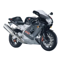
Coils (4) and (5) are so placed that the connector
is suitably positioned.
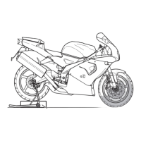
Clamp (6) locks the left coil supply cable.
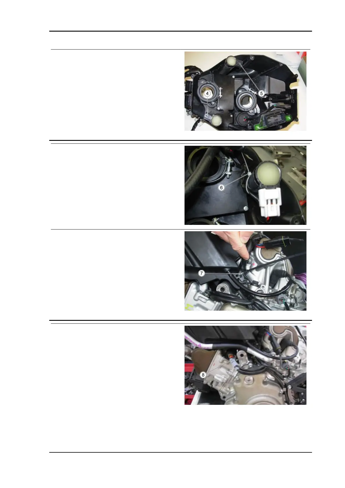
The main cable harness must also be secured ex-
ternally by locking it to the filter housing with clamp
(7) on the left side.
The connectors of both current generator and rev-
olution/timing sensor are protected by a rubber
cover (8) and inserted under the filter housing be-
tween the front and rear heads.
MXV 450 Electrical system
ELE SYS - 49