VAR4 / VAR12 / VAR20 - Operation Manual
Is
Page 193 of 308
15
5
sue: 03 complete, approved
14 Contact Configuration
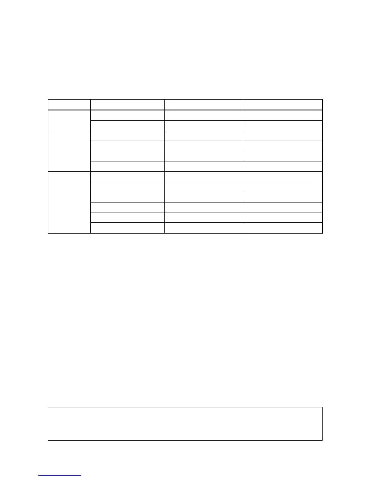
The VAR Router provides up to 6 control ports each of them with a number of contacts, as described in
Table .
Table 1 VAR Router Control Ports
VAR Router Port Type Control Port Number Contacts
VAR4 Analogue Port-1 1 – 10
Opto-Isolated Port-2 11 – 22
VAR12 Analogue Base Unit - Port-1 1 – 10
Opto-Isolated Base Unit - Port-2 11 – 22
Opto-Isolated Expand Unit 1 - Port-1 23 – 31
Opto-Isolated Expand Unit 1 - Port-2 32 – 42
VAR20 Analogue Base Unit - Port-1 1 – 10
Opto-Isolated Base Unit - Port-2 11 – 22
Opto-Isolated Expand Unit-1 - Port-1 23 – 31
Opto-Isolated Expand Unit-1 - Port-2 32 – 42
Opto-Isolated Expand Unit-2 - Port-1 43 – 51
Opto-Isolated Expand Unit-2 - Port-2 52 – 62
Any contact may be configured as:
• Latent route trigger
The contact triggers a latched or non-latched latent route, or a route where the associated DVAs are
played once only.
When configured to trigger a latched latent route, a separate contact must be specified as a reset
contact.
See Section “14.2 Configuring a Contact for Routing”.
• External fault input
The contact is configured as fault status inputs from external equipment.
See Section “14.3 Configuring a Contact as an External Alarm”.
• Remote fault accept
The contact acts as a local fault accept button of a remote fault panel.
See Section “14.4 Configuring a Contact as Remote Fault Accept”.
See Section “9.2 Contact Music Selector Configuration”.
• Music A/B selector
The contact is configured as a control to switch between Music A and Music B phono inputs.
L
Contacts 1 to 10 only use a non-isolated analogue interface with an internal pull-up to 5V and
may operate in two modes: ‘non-monitored’ to interface a simple contact closure to ground; or
‘monitored’ to interface resistively monitored contacts. Each contact is individually selectable
between these two modes, as described in the following sections.