VAR8 and Variants Operation, Commissioning, Fault Finding, and Maintenance Guide -
Is
Page 133 of 166
sue: 02 complete, approved
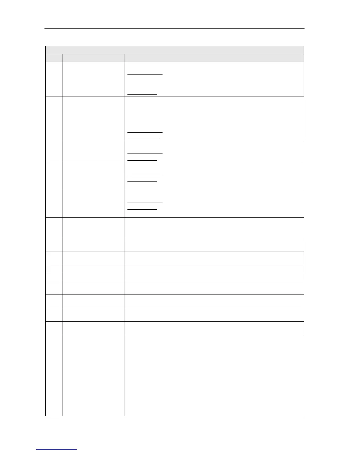
VAR8 Menu Description
Ref. Item Description/Possible Settings
49 Frequency Defines the type of input surveillance tone to monitor.
Possible values:
LF Surv (Low Frequency)
HF Surv (High frequency )
No Surv (none)
Default value:
‘Not-Surv’
50 Thresholds Defines the input and output surveillance tone limits in millivolts.
The surveillance type (LF or HF) must have been already set in the ‘Frequency’
sub-menu (see item 49). The selected mainframe continuously determines the
thresholds for the input and output AC levels based upon a fixed proportion of
the levels being detected. The Router presents these levels to the LCD display.
Possible values:
In(mV)=0000 to 2000 Out(mV)=0000 to 2000
Default values:
‘In(mV)=0000’ and ‘Out(mV)=0000’
51 Interval Defines the maximum interval between surveillance tones (for pulsed operation).
Possible values:
00 to 50
Default value:
‘Interval(s)=00’
52 Not Surv Enables DC surveillance to be set on or off.
Possible values:
‘Not Surv’ or ‘Surveyed’
Default value:
‘Not Surv’
Select SET to commission the parameter.
53 Spurs=00 Enables the number of spurs for fault detection to be set.
Possible values:
00 to 10
Default value:
‘Spurs=00’
Select SET to commission the parameter.
54 Read
Displays the number of spurs calculated by the amplifier frame software from the
DC line resistance reading.
‘Read’ is only possible if DC surveillance is ‘Surveyed’.
55 Surv In
Displays the monitored level of the surveillance tone detected at the selected
amplifier input.
56 Surv Out
Displays the monitored level of the surveillance tone detected at the selected
amplifier output.
57 DC Line Displays the speaker line DC reading and the number of spurs.
58 Earth Leak Displays the earth leakage reading.
59 Router
Access to the Router configuration functions: inputs, outputs, control port, etc.:
ROUTING CHANNEL/ROUTE MENU.
60 Network
Access to Network configuration: network address and channels, priority, name,
and Audio Control Unit type.
61 Misc
Access to the software versions, temperature settings, fault log clear, and RS-
232 port configuration: SYSTEM MISC MENU.
62 View
Access to functions to scroll through configured amplifier frames and slots:
SYSTEM VIEW MENU.
63 Learn
Causes the Router to interrogate the audio-CAN bus, and discover what frames
and amplifiers are configured.
After detecting all the frames, the FRAME COMMISSIONING sub-menu is
displayed, allowing the user to commission the detected frames and amplifiers.
‘S’ identifies a standby amplifier
‘N’ identifies a single circuit surveillance mode
‘D’ identifies a dual circuit surveillance mode
‘L’ identifies a loop return surveillance mode
The act of commissioning commands the frame to recognise the current amplifier
installation as the correct one, i.e. if an amplifier is removed and no longer
required, until the frame is re-commissioned a fault will be reported that the
amplifier is not present. Once re-commissioned the frame will recognise that the
missing amplifier is correctly missing and stop reporting a fault.