V9.7 01/05/20 UD0011 Page 167 of 177
This Document is uncontrolled when printed unless over stamped “CONTROLLED DOCUMENT"
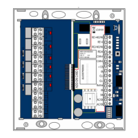
18.7.5 BATTERY CONNECTION DETAILS
The following diagram shows the connection details for the Traka Touch Backup Battery. For details on where to connect
the battery to the Traka Touch PCB refer to the ‘Traka Touch PCB’ section.
NOTE: Depending on your system type the battery may differ slightly from the image below. However, the
connection details remain the same.
For Battery disconnection, carefully disconnect the spade connectors from the battery.
WARNING: Never disconnect the wires from the green connector whilst the cable is still connected to the
battery terminals.
NOTE: Ensure that the spade connectors are pushed fully onto the battery terminals. It is recommended
that insulation tape is wrapped around the battery to fully cover any exposed parts of the battery terminals.
 Loading...