ENL CC x
12.
Verify normal service level; first, switch the active clock to standby using:
LD 60
SWCK x
If an error message results, refer to Avaya Communication Server 1000M and
Meridian 1 Large System Maintenance (NN43021-700) for the interpretation.
Note:
Switching clock controllers using LD 60 will generate ERR20 messages.
These can usually be ignored, but avoid excessive switching, especially when
counters are near the maintenance or out-of-service thresholds. Excessive
switching can generate maintenance or out-of-service threshold messages, or
cause the PRI to be disabled.
Check the counters in LD 60. If necessary, reset the counters using the RCNT
command.
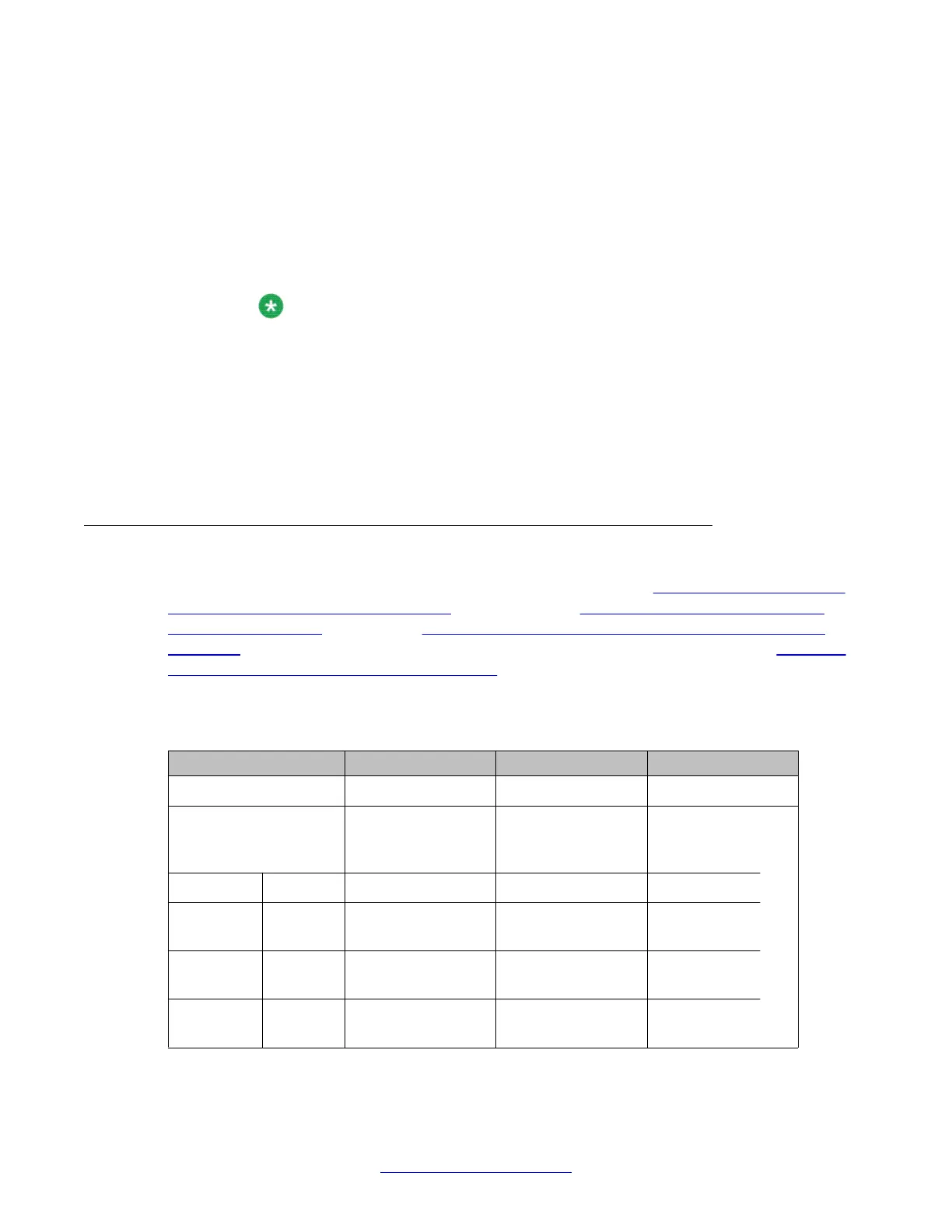
Set switches
Before installing a clock controller
, set the switches as shown in
Table 23: Clock controller
switch settings for QPC471 vintage H on page
82 and
Table 24: Clock controller switch
settings for QPC775 on page 83. Table 23: Clock controller switch settings for QPC471
vintage H on page 82
displays the settings for different vintages of the QPC471.
Table 24:
Clock controller switch settings for QPC775 on page 83 shows the settings for the
QPC775.
T
able 23: Clock controller switch settings for QPC471 vintage H
System SW1 SW2 SW4
51C, 61C on on on on off off off off off on * *
Cable length between
the J3 faceplate
connectors:
0-4.3 m (0-14 ft.) off
off
4.6–6.1m (15–50
ft.)
off
on
6.4–10.1m (21–33
ft.)
on
off
10.4–15.2
m
(34–50
ft.)
on
on
Clock controller maintenance
82 ISDN Primary Rate Interface Maintenance November 2011
Comments? infodev@avaya.com
 Loading...