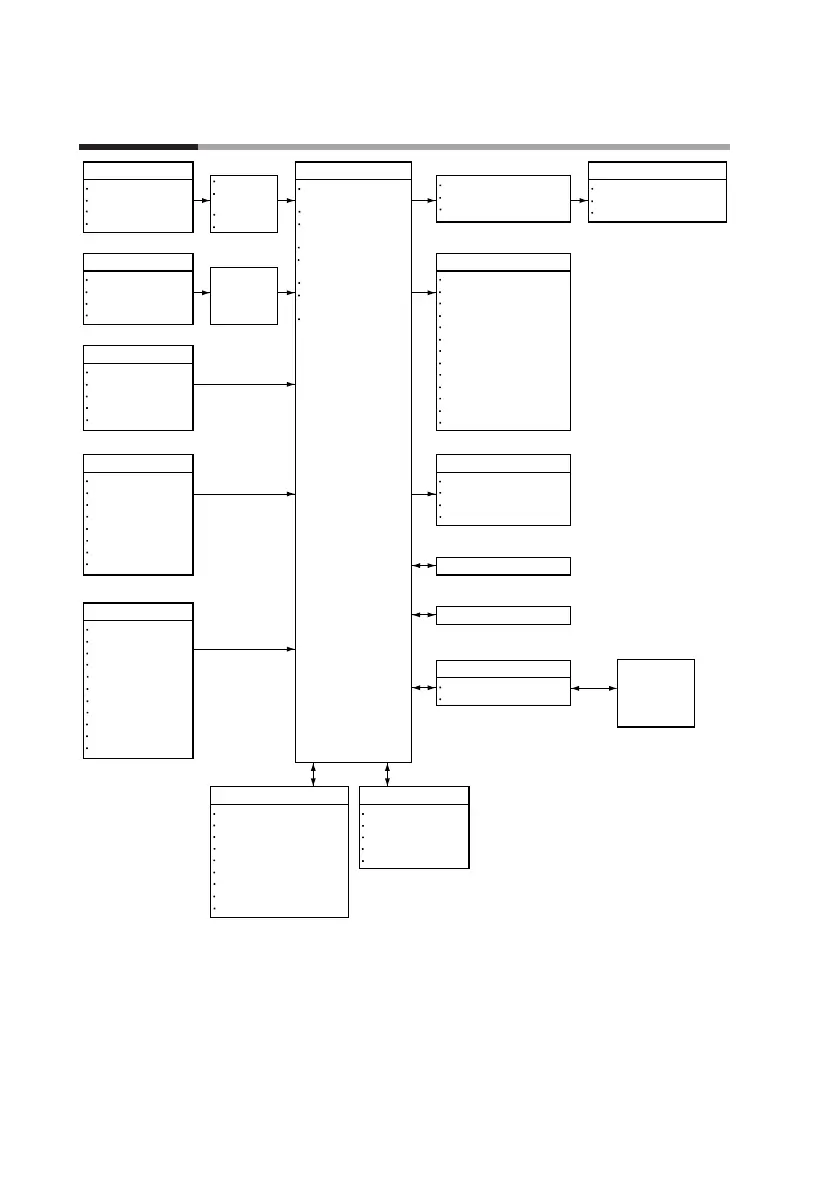
1 - 2 Basic Function Block Diagram
1-2
Chapter 1. PRODUCT OUTLINE
Input 1
Input 2
•
Root extraction
•
Approximation by
linearization table
•Bias
•Filter
External switch input: 12 points
External switch input: 4 points
Key operation
Control operation unit
Event output : 16 points
Time event
PV
SP
Deviation
MV
Code
Code with a timer
Each mode
Alarm
Segment No. code
Specific segment
Program No. code
PV change rate
Auxiliary output : 1 point/2 points
PV
SP
Deviation
MV
RS-485/RS-232C communication input/output
Loader communication input/output
Memory card
Output
Memory Card
Reader Writer
+
Smart Loader
Package
*
1
Program Parameter
*
1 : Option for some models
*
2 : Option
*
2
*
2
*
3
*
1
Program
Parameter
Variable parameter
Event configuration
PID parameter
Setup
Constant value control
99 pattern X 99 segment
Event
PID group/output limiter group
G.SOAK
PV shift
Repeat
PV start
Cycle
Pattern link
Display selection
Program No.
RUN/HOLD
RESET
ADV
FAST
AUTO/MANUAL
AT
Program setting
Parameter setting
Memory card operation
FAST
RAMP-E
AUTO/MANUAL
AT
G.SOAK reset
Forward-reverse operation
Auto load
PV1/PV2 selection
RUN
HOLD
RESET
ADV
Program No.
Thermocouple
Resistance temperature detector
DC current
DC voltage
Thermocouple
Resistance temperature detector
DC current
DC voltage
Root extraction
Approximation by
linearization table
Bias
Filter
Mode transition
PID control
Auto tuning
Forward-reverse operation
ON-OFF control
SP limit
SP bias
PV2 channel selection
Output change limit
Upper and lower limit
SP output
Current proportionality
Volt-time proportionality
Open collector time proportionality
*
3 :
This function is available on the
DCP551A
*****
model only.

 Loading...


