EasyManua.ls Logo

Azbil dcp551 mark II - Isolation During Input;Output

Azbil dcp551 mark II
220 pages
To Next Page IconTo Next Page
To Previous Page IconTo Previous Page
Loading...
4 - 12 Isolation During Input/Output
4-18
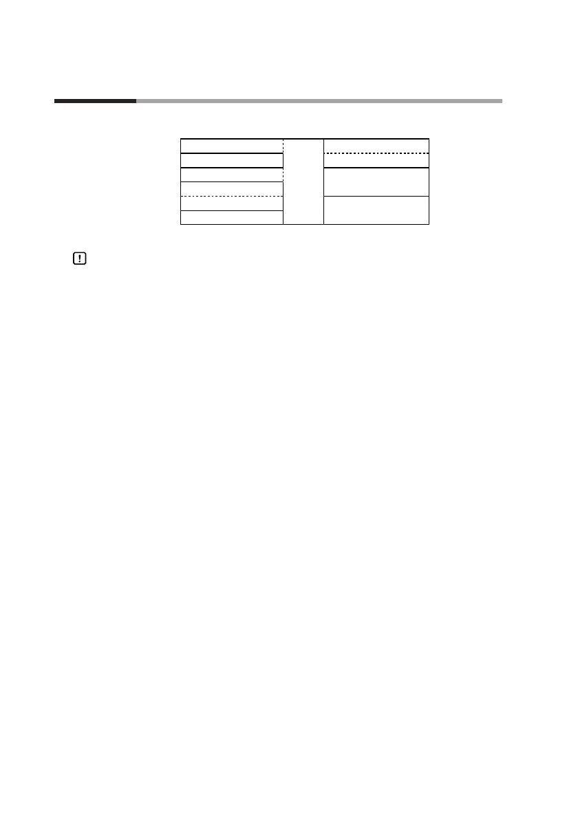
Isolation between inputs and outputs are shown below. In this figure, the solid lines enclose mutually-isolated
sections. Those sections bounded by dashed lines are not isolated.
Handling Precautions
The terminal base is not isolated from internal digital circuits.
When not in use, always replace the cap.
PV input CH1
PV input CH2
Digital
circuit
Control output
Auxiliary output CH1
Loader communication
External switch input
Auxiliary output CH2
Communication
Event output
Memory card input*
* : available on the DCP551A***** model only
Chapter 4. WIRING

Table of Contents

Related product manuals