Home
Azbil
Controller
dcp551 mark II
Azbil dcp551 mark II User Manual
5
of 1
of 1 rating
220 pages
Give review
Manual
Specs
To Next Page
To Next Page
To Previous Page
To Previous Page
Loading...
6-6
■
Constant value contr
ol mode
●
DISP key function
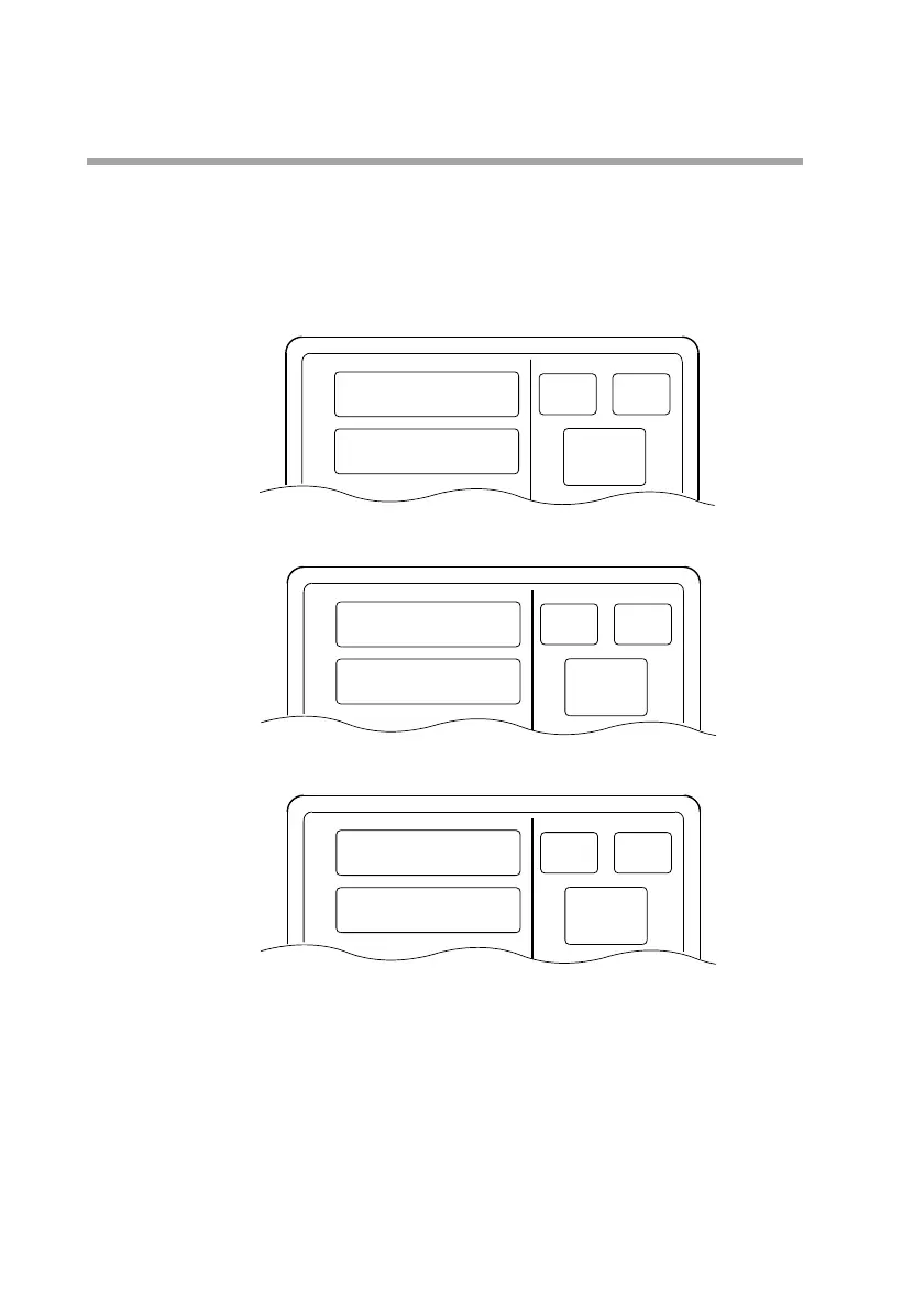
The DISP key is used to cycle through the displays in the following order: Display
C1, display C2, display C3, display C1.
●
Display C1
●
Display C2
●
Display C3
In MANUAL mode, the number of digits available for output values flash.
OUT
PV
PROG
SEG
PROFILE
PV
Output value (%)
DEV
PV
PROG
SEG
PROFILE
PV
Deviation
PV
SP
PROG
SEG
PROFILE
PV
SP
Chapter 6. OPERATION
97
99
Table of Contents
Default Chapter
8
Table of Contents
8
Chapter 1. PRODUCT OUTLINE
15
Features
15
Basic Function Block Diagram
16
Data Configuration Overview
17
System Configuration
18
CPL Communications Network-Based Configuration
18
Model Number
19
Chapter 2. NAMES and FUNCTIONS of PARTS
21
Structure
21
Console
22
Basic Display Status
22
Display
22
Key Pad
24
Key Chord Functions
26
Loader Jack
27
Input Type and Range Number
28
Input
28
Chapter 11 . DISPOSAL
31
Chapter 12 . SPECIFICATIONS
31
Specifications
31
Sources of Electrical Interference and Countermeasures
32
Installation
33
Panel Cutout Dimension
33
Installation Procedures
34
Chapter 3. INSTALLATION and MOUNTING
31
Before Installation
31
Mounting Position
31
Chapter 4. WIRING
35
Precautions on Wiring
35
Recommended Cables
37
Making Terminal Connections
38
Dcp551
38
Terminal Array
39
Power Supply and Grounding
40
Power Supply
40
Grounding
40
PV Input (Analog Input) Connection
41
PV Input CH1 Connection
41
PV Input CH2 Connection
41
Control Output Connection
43
Current Output (5G, 5S)
43
Voltage Output (6D)
43
Open Collector Output (8D)
43
Auxiliary Output (Output CH1, CH2) Connection
44
Auxiliary Output CH1 Connection
44
Auxiliary Output CH2 Connection
44
Event Output (Open Collector Output) Connection
45
External Switch Input Connection
46
Communication Connection
47
RS-232C Connection
50
Connection to ST221
51
Isolation During Input/Output
52
Chapter 5. FUNCTIONS
53
Data
53
Data Types
53
Program Pattern
54
Pattern
54
Events
57
PID Group Selection
68
G.SOAK (Guarantee Soak)
69
PV Shift
70
Repeat
71
PV Start
72
Cycle
73
Pattern Link
74
Tag
75
Mode
76
Mode Types
76
Mode Transitions
78
Mode Transition Operations
79
Mode Transition Restrictions
80
Controllers and Programmers
81
Input Process Functions
82
PV Input 1 Channel Model
82
PV Input 2 Channel Model
83
Channel Switching (PV Input 2 Channel Model)
84
Output Processing Functions
89
SP Output
91
Chapter 6. OPERATION
93
Power Supply on
93
Basic Display Selection
94
Program Run Mode Displays
95
Constant Value Control Mode
98
Selecting Programs
99
Selecting Program Numbers
99
External Switch Operation
100
External Switch Input
100
Selecting Programs
101
Read Timing
103
Manual Operation and Auto-Tuning
104
Manual Operation
104
Auto-Tuning (AT)
104
Chapter 7. PARAMETER SETUP
107
Parameter Setup
107
Selecting Parameter Settings Groups
107
Progression of Individual Items in Parameter Settings
107
Modifying Individual Items and Exiting the Setting Mode
108
Parameter Setting List
110
Variable Parameter Setting
111
Detailed Information on Variable Parameters
115
Event Configuration Data Settings
118
Settings by Event Type
119
PID Parameter Setting
124
Setup Data Setting
127
Detailed Descriptions of Setup Data Settings
134
Constant Value Control Data Setting
140
Chapter 8. PROGRAM SETUP
141
Selecting Number of Program to Operate
141
Starting Programming
142
State Transition
142
Programming Map
144
Display Items
145
Setting Pattern Items
145
Setting Event Items
147
Setting PID Groups and Output Limiter Group Number Items
152
Setting G.SOAK (Guarantee Soak) Items
153
Setting PV Shift Items
154
Setting Repeat Items
155
Setting PV Start Items
156
Setting Cycle Items
157
Setting Pattern Link Items
158
Setting Tag Items
159
Deleting Programs
160
Inserting and Deleting Segments
161
Copying Programs
163
Program Copy Procedures
163
General Reset
164
General Reset Procedures
164
Chapter 9 . MEMORY CARD OPERATIONS
165
Memory Card Type and Functions
165
Save Procedures
166
Save Menu
166
Procedures for Formatting Cards
167
Procedures for Saving Single Programs
167
Procedures for Saving All Programs
168
Procedures for Saving Setup Data
168
Procedures for Saving Variable Parameters
168
Procedures for Saving PID Parameters
169
Procedures for Saving Event Configuration Data
169
Procedures for Saving All Parameters
169
Load Procedures
170
Load Menu
170
Card Battery Alarm Panel
171
Procedures for Loading Individual Programs
171
Procedures for Loading All Programs
172
Procedures for Loading Setup Data
172
Procedures for Loading Variable Parameters
172
Procedures for Loading PID Parameters
172
Procedures for Loading Event Configuration Data
173
Procedures for Loading All Parameters
173
Autoload
174
Key Operated Autoload Procedure
174
Auto Load Using External Switch Inputs
175
Error Message List
176
Chapter 10 . MAINTENANCE and TROUBLESHOOTING
177
Self-Diagnostic Functions and Alarm Code Displays
177
Alarm Code Display
178
Normal Display Mode Problems
179
Parameter Setting Related Problems
182
When the BAT LED Flashes
184
Attachment/Auxiliary Devices List
197
External Dimensions
198
5
Based on 1 rating
Ask a question
Give review
Questions and Answers:
Need help?
Do you have a question about the Azbil dcp551 mark II and is the answer not in the manual?
Ask a question
Azbil dcp551 mark II Specifications
General
Brand
Azbil
Model
dcp551 mark II
Category
Controller
Language
English
Related product manuals
Azbil C36
16 pages
Azbil C7G
426 pages
Azbil C26
16 pages
Azbil C15
150 pages
Azbil SDC26
16 pages
Azbil SDC46
80 pages
Azbil SDC45
80 pages
Azbil SDC15
146 pages
Azbil AUR450C
62 pages
Azbil KZ03 Series
16 pages
Azbil AUR890 Series
62 pages
Azbil BH-101G0W0000
20 pages