Description
34
7990087_030_03 – 2080492 – 2023-01-19
in the set swivel position, or can only be moved with difficulty, the
brake force must be adjusted by staff trained in this work by
Baxter.
If the braking force needs to be adjusted on multiple support arm
components, use the following sequence:
1. Brake screw [A] for the brake of the extension arm
2. Brake screw [B] for the brake of the spring arm
3. Brake screw [C] for the optional braking of the comfort
bracket
4. Brake screw [D] for brake of the 1/4 bracket
5. Brake screw [E] for the braking of the light head
The weight of the support arm component is compensated by a
spring installed in the spring arm. If the spring arm does not remain
stable in the selected height position, the spring force must be
adjusted by staff trained in this work by Baxter. If the spring arm
creeps upwards, the spring force is too high. If the spring arm
creeps downwards, the spring force is too low.
The swivel range of the spring arm upwards and downwards can
be individually adjusted by staff trained in this work by Baxter. The
swivel range can be limited up to a fully horizontal position.
4.7 Visual indicators and displays
4.8 TruRemote software
The Mobile Control 7,9 and Wall Control Panel control units are
equipped with the TruRemote software and have a graphic user
interface.
The Mobile Control 7,9 and Wall Control Panel can be used to
operate up to 3 iLED 7 surgical lights in a single light system.
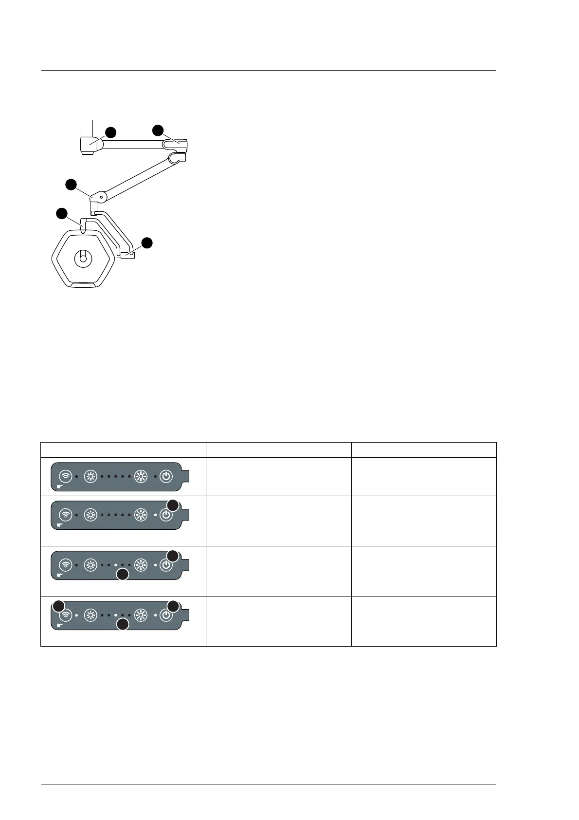
Display Status Meaning
No indicator is illuminated. The external power supply of
the surgical light is switched
off.
The indicator next to the [i1] key
lights up.
The external power supply of
the surgical light is switched on.
The surgical light is switched
off.
The indicator next to the [i1] key
and the middle indicator for
lighting intensity [a1] light up.
The surgical light is illuminated,
but is not connected to the
Mobile Control 7,9 / the
Wall Control Panel.
The indicator next to the [i1] key
and the middle indicator for
lighting intensity [a1] light up,
along with the [i4] indicator.
The surgical light is illuminated
and can be controlled with the
Mobile Control 7,9 / the
Wall Control Panel.
3 sec.
3 sec.
i1
a1
3 sec.
i4
i1
a1