Use
7990087_030_03 – 2080492 – 2023-01-19 59
8. Mount the front cover on the spring arm [9].
a) Position the right front cover [D] on the spring arm so that
there is a gap [I] between the connecting pin of the
adaptation [H] and the cover.
b) Attach the right front cover to the spring arm with 3 PT
screws [E] (Torx T10 screwdriver).
c) Position the left front cover [A] on the spring arm so that
there is a gap [I] between the connecting pin of the
adaptation [H] and the cover and so that, at the joint
between the two front cover panels, all catches slide into
one another and engage.
d) Fasten the left front cover with 1 MLF screw and its washer
[C] (Torx T10 torque screwdriver with a torque of 1 Nm /
0.73 ft lb) on the spring arm.
e) Insert 1 PUSH-button [B] flush into the left front cover. The
PUSH-button may not protrude from the cover.
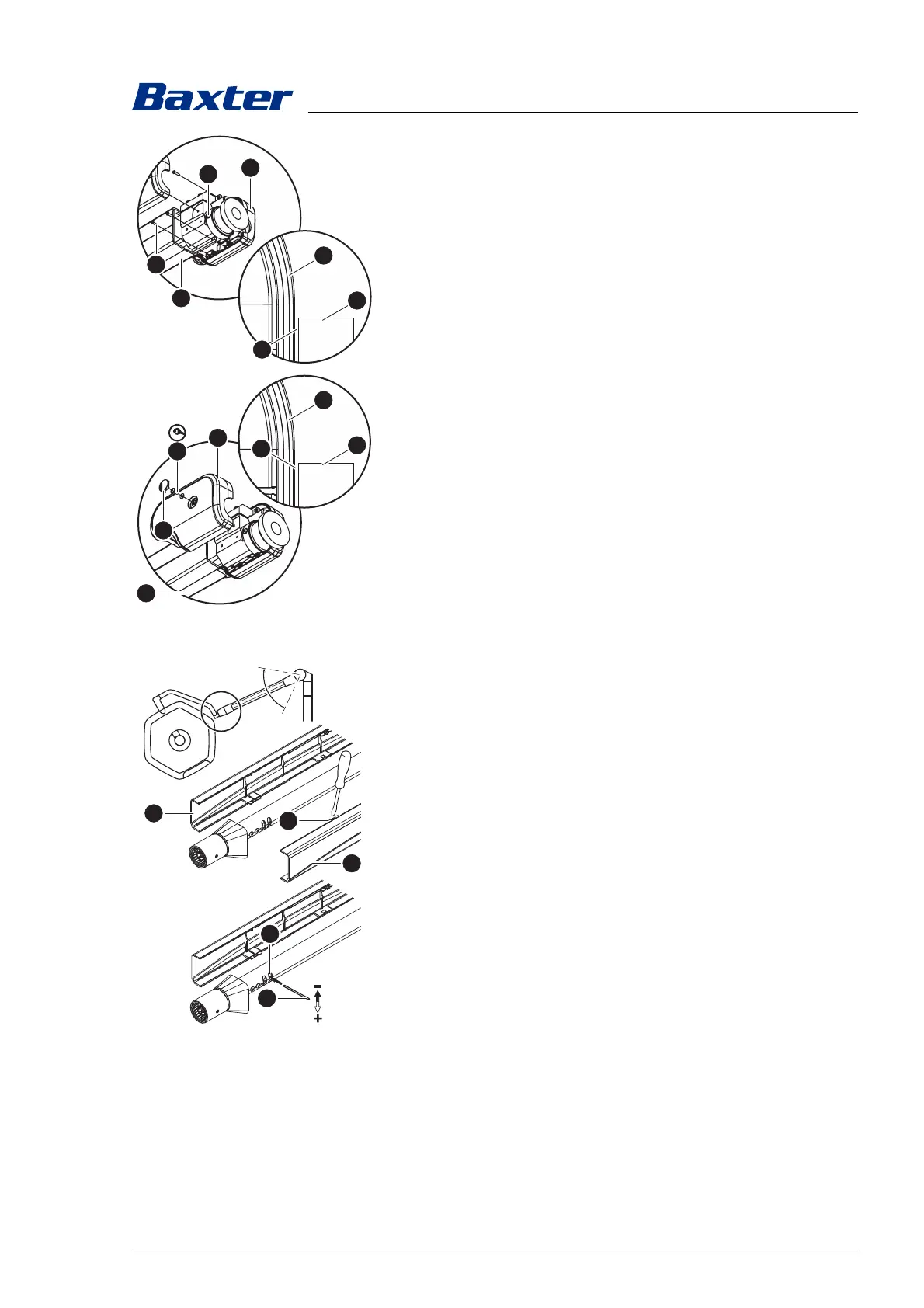
5.14.3 AC 2000 NRH mobil spring arm
1. Switch off the surgical light at a control module and
disconnect it from the mains power (see Chapter 5.7).
2. Separate the two cover halves [A] from each other and
remove them. To do this, press the six tabs [B] on the
cladding, using a slotted screwdriver.
3. Insert the pin [C] into setting opening [D] and set the swivel
range.
– Reduce the swivel range:
Push the pin upwards.
– Increasing the swivel range:
Push the pin downwards.
4. Position the two cladding halves on the spring arm and press
them together, so that the six tabs engage.
5. Check that the covers are securely attached.
6. Test the swivel range. Collisions must be avoided.