Use
60
7990087_030_03 – 2080492 – 2023-01-19
5.15 Adjusting the optional brakes on the spring arm
The braking force should only be set by personnel who have been
trained by Baxter in this work.
5.15.1 Spring arm L21
1. Switch off the surgical light at a control module and
disconnect it from the mains power (see Chapter 5.7).
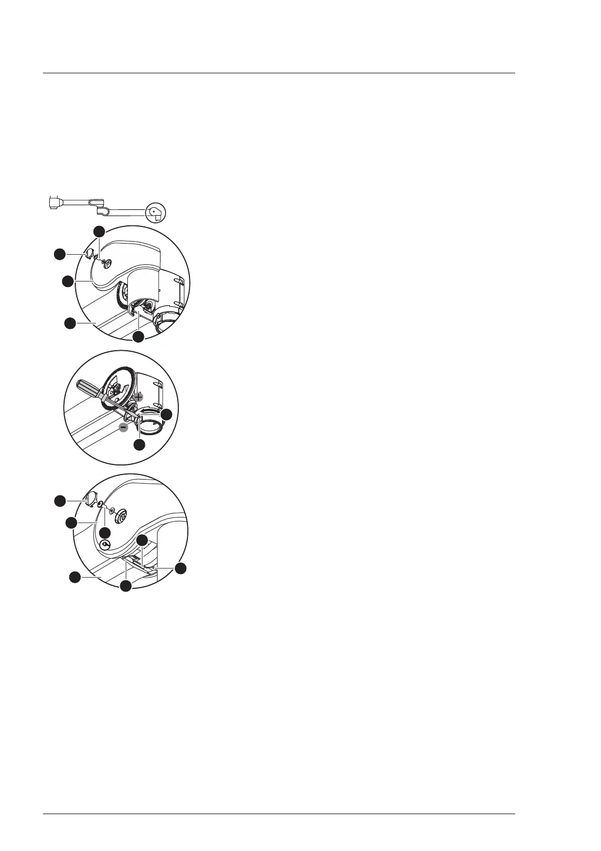
2. Remove the front cover [A] from the spring arm [7].
a) Press and remove the PUSH button [B] from the right and
left front spring arm cover respectively.
b) Using a Torx T10 screwdriver, remove 1 MLF screw and its
washer [C] from each of the right and left front spring arm
covers.
c) Carefully unlock all catches at the joint between the two
cover panels.
d) Remove the front spring arm covers from the spring arm.
3. Manually push the upper and lower faceplates [D] into the
side cover of the spring arm.
4. Adjust the brake [F] with a suitable flathead screwdriver.
– Increase the braking force:
Turn the flathead screwdriver clockwise.
– Reduce the brake force:
Turn the flathead screwdriver in an anticlockwise direction.
5. Test the braking strength. The support arm component must
be easily adjustable and remain steadily in the set swivel
position.
6. Mount the front cover [A] on the spring arm [7].
a) Rotate the recess of the segment safety catch [G] over
the optional brake screw.
b) Position the right and left front spring arm covers on the
spring arm so that, at the joint between the two front
cover panels, all catches slide into one another and
engage.
c) Fasten the right and left front spring arm cover with one
MLF screw and one washer [C] (Torx T10 torque
screwdriver with a torque of 1 Nm/0.73 ft lb) each on the
boom.
d) Insert 1 PUSH-button [B] flush into each of the right and
left front spring arm cover. The PUSH-button may not
protrude from the cover.
7. Close the upper and lower faceplate [D].
a) Manually pull the upper and lower faceplate out of the side
cover in a forward direction and insert the 2 catches [H]
into the front spring arm cover.
b) Push the face plates further into the cover with a suitable
flathead screwdriver, slightly press them upwards and
guide the locking hooks [I] into the front spring arm cover.