Use
42
7990087_030_03 – 2080492 – 2023-01-19
3. Mobile Control 7,9
4. Wall Control Panel
Simultaneous activation of keys on various control units leads to
execution of functions in order of priority.
Any setting of the surgical light, irrespective of whether it is
performed with the Mobile Control 7,9, the Wall Control Panel, the
SLC handle adapter or directly at the control unit, will be
simultaneously shown on the other control units and the
corresponding control screen of the Mobile Control 7,9 and
Wall Control Panel. The change is displayed in both the
Information area and on the device display and the corresponding
setting areas or operating options. The user always sees the
current settings for the surgical light on all operating units.
Multiple Mobile Controls 7,9 and Wall Control Panel units may be
used in one room. Where the surgical light is operated with two
Mobile Control 7,9 or Wall Control Panel units simultaneously, only
the last operator input made to the surgical light will be executed.
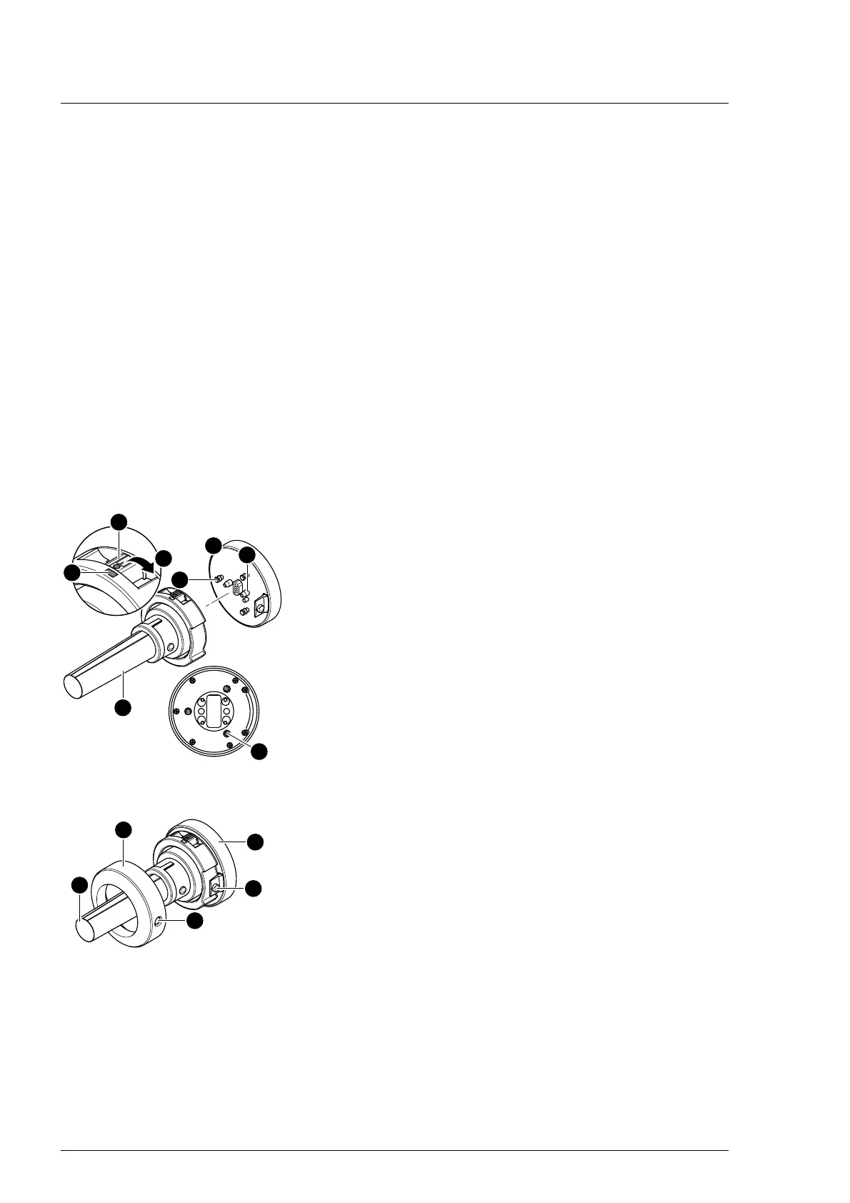
5.4 Attaching the handle adapter
5.4.1 Adaption disposable handle/Adaption Standard handle
1. Slide the locking device of the bayonet lock [A] downwards
into position [B] so that the three shut-off openings [C] of the
base plate are released.
2. Align the handle adapter [16] so that the arrangement of the
three bayonet pins [D] and the two centering pins [E] of the
mount [F] on the camera bracket are aligned with the
shut-off openings [C] in the base plate (the camera plug
connector will then also be aligned).
3. Insert the handle adapter [16] on the mount [F] of the lamp
head.
4. To secure it in place, slide the locking device of the bayonet
lock [A] upwards so that the two red marking dots [G] are
aligned.
5. NOTICE! Check the secure position of the handle adapter on
the mount. After locking the bayonet lock, always make sure
to check that the handle adapter is securely seated on the
mount.
6. Slide the cover (metal ring) [H] onto the handle adapter [16]
and the mount of the lamp head. Ensure that the plastic
catch [I] of the mount [F] is correctly engaged in the securing
hole [K] on the cover [H].