Use
7990087_030_03 – 2080492 – 2023-01-19 55
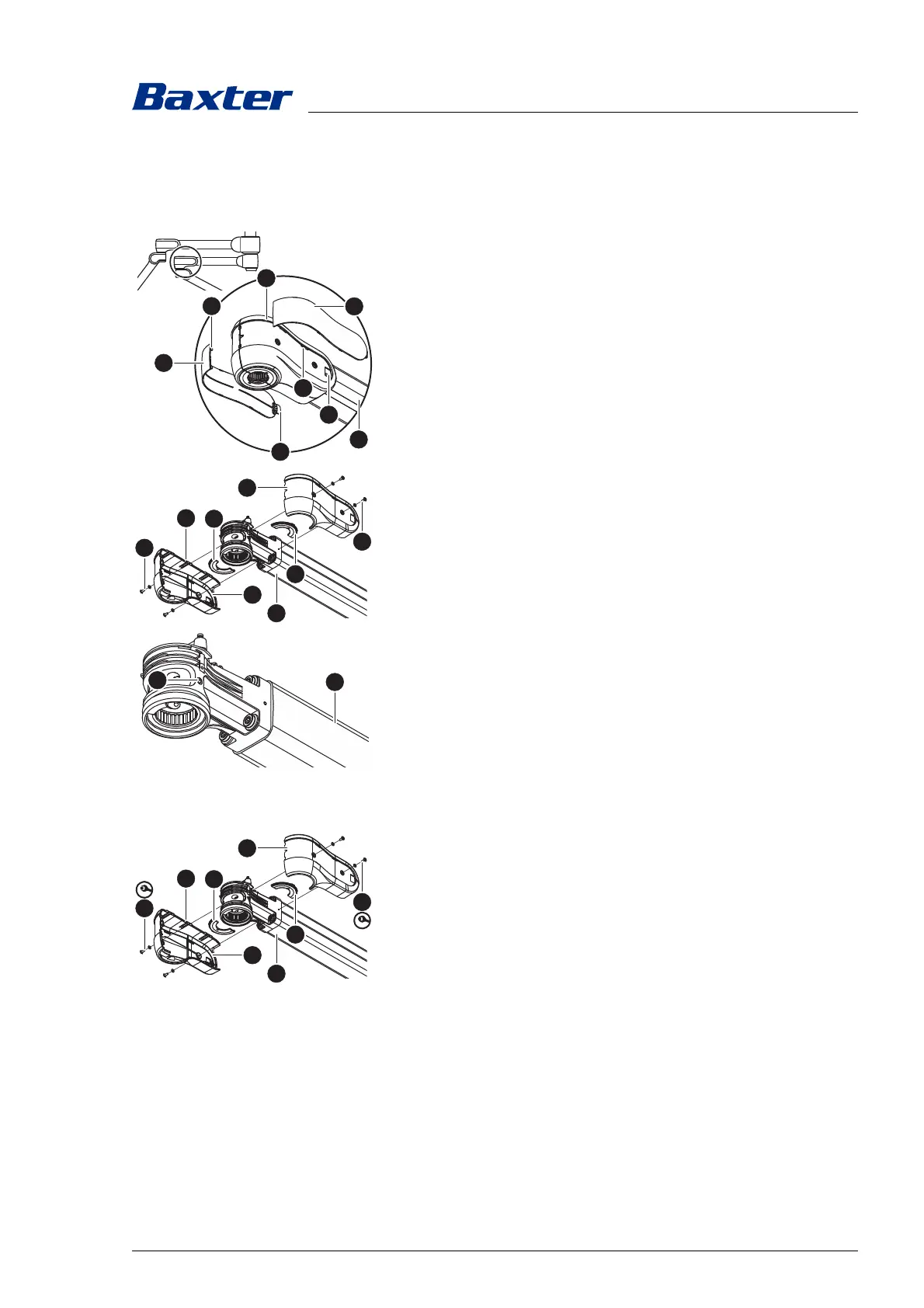
5.12.3 Spring arm
There are 2 opposing brake screws on each boom.
1. Switch off the surgical light at a control module and
disconnect it from the mains power (see Chapter 5.7).
2. Remove the decor caps [A] of the socket cover [B].
a) Lightly press in the right and left decor caps near the lugs
[C] and pull the decor caps out of the openings [D].
b) Carefully open the locking mechanisms [E] of the decor
caps.
c) Feed the right and left decor cap out of the mounts [F] and
remove.
3. Remove the socket cover [B] from the boom [4].
a) Using a Torx T10 screwdriver, remove 2 MLF screws and
their washers [G] from each of the right and left socket
covers.
b) Carefully open the locking mechanisms [H] of the socket
cover.
c) Remove the right and left socket cover together with the
optional faceplates [I] from the boom.
4. To adjust the brake force, alternately turn both opposite
brake screws [J] by the same number of rotations with a
Size 5 Allen key.
– Increase the braking force:
Turn the Allen key clockwise.
– Reduce the brake force:
Turn the Allen key in an anticlockwise direction.
5. Test the braking strength. The support arm component must
be easily adjustable and remain steadily in the set swivel
position.
6. Mount the socket cover [B] on the boom [4].
a) Fasten the right socket cover together with the optional
faceplate [I] with 2 MLF screws and washers [G] (Torx T10
torque screwdriver with a torque of 0.5 Nm/0.37 ft lb) on
the boom.
b) Position the left socket cover together with the optional
faceplate [I] on the right socket cover so that all locking
mechanisms [H] are pushed together and engage.
c) Fasten the left socket cover with 2 MLF screws and
washers [G] (Torx T10 torque screwdriver with a torque of
0.5 Nm/0,37 ft lb) on the boom.
7. Check the secure fit of the socket cover with the optional
faceplates on the boom.
– The covers on the boom must be connected to one another
with the least possible gap.
– Each socket cover must be attached with 2 MLF screws and
washers.