Use
58
7990087_030_03 – 2080492 – 2023-01-19
8. Mount the front cover [A] on the spring arm [7].
a) Rotate the recess of the segment lock [G] over the
optional brake screw or the brake screw opening [H].
b) Position the right and left front spring arm covers on the
spring arm so that, at the joint between the two front
cover panels, all catches slide into one another and
engage.
c) Fasten the right and left front spring arm cover with one
MLF screw and one washer [C] (Torx T10 torque
screwdriver with a torque of 1 Nm/0.73 ft lb) each on the
boom.
d) Insert 1 PUSH-button [B] flush into each of the right and
left front spring arm cover. The PUSH-button may not
protrude from the cover.
9. Close the upper and lower faceplate [D].
a) Manually pull the upper and lower faceplate out of the side
cover in a forward direction and insert the 2 catches [I]
into the front spring arm cover.
b) Push the face plates further into the cover with a suitable
flathead screwdriver, slightly press them upwards and
guide the locking hooks [J] into the front spring arm cover.
10. Move the spring arm upwards and downwards. Check the
secure fit of the upper and lower faceplate while doing so.
– The locking hooks must engage with the front spring arm
cover.
– The plates must slide easily in the lateral guides.
5.14.2 Spring arm LCH19
1. Switch off the surgical light at a control module and
disconnect it from the mains power (see Chapter 5.7).
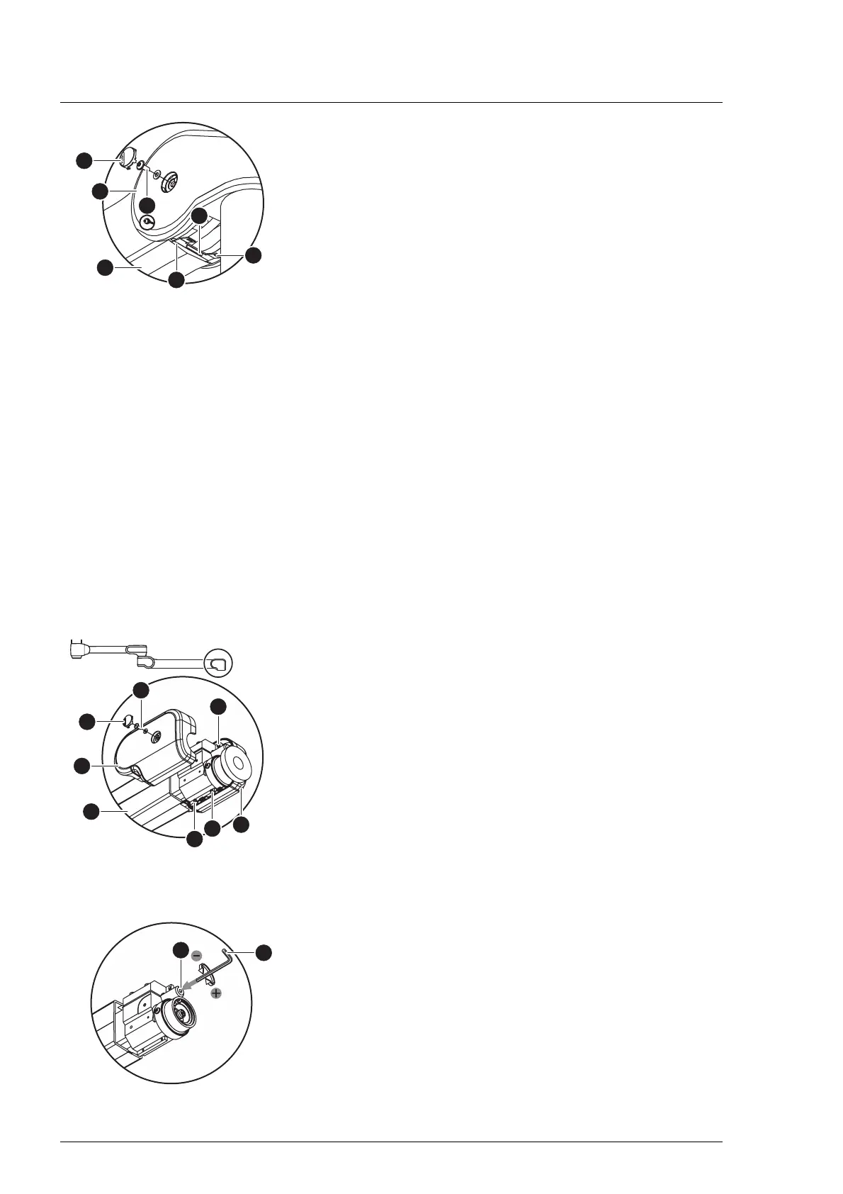
2. Pull the spring arm [9] down to relieve the setting screw.
3. Remove the left front cover [A] from the spring arm [9].
a) Press and remove the PUSH-button [B] from the left front
spring arm cover.
b) Using a Torx T10 screwdriver, remove the MLF screw and
its washer [C] from the left front cover.
c) Carefully unlock the catches of the left front panel at the
connecting edge between the two cover panels.
d) Remove the left front cover from the spring arm.
4. Remove the right front cover [D] from the spring arm [9].
a) Using a Torx T10 screwdriver, remove 3 PT screws [E] from
the right front cover.
b) Remove the right front cover from the spring arm.
5. Insert a Size 5 Allen key [F] into the adjustment opening [G].
6. Adjust the swivel range.
– Reducing the swivel range:
Turn the Allen key in an anticlockwise direction.
– Increasing the swivel range:
Turn the Allen key clockwise.
7. Test the swivel range.