Use
52
7990087_030_03 – 2080492 – 2023-01-19
15. Remove all sterilizable handles/disposable handles/
disposable sleeves from the surgical lights.
5.12 Adjusting the braking force at the boom and spring arm
The braking force should only be set by personnel who have been
trained by Baxter in this work.
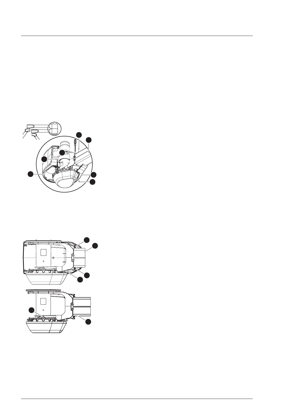
5.12.1 C boom
There are 2 opposing brake screws on each boom.
1. Switch off the surgical light at a control module and
disconnect it from the mains power (see Chapter 5.7).
2. Remove the left back cover [A] from the boom [4].
a) Turn the boom so that the upper PT screw [B] is
accessible.
For better access to the PT screw, remove the rear cover
of the boom above it.
b) Using a Torx T10 screwdriver, remove the upper and lower
PT screw [B] on the left rear cover.
c) Insert a suitable flathead screwdriver into the mounting
opening [C] of the left rear cover.
d) Press the flathead screwdriver slightly upwards and
release the cover.
e) Insert the flathead screwdriver into the mounting opening
[D] of the right rear cover [E].
f) Press the flathead screwdriver slightly downwards and
release the cover.
g) Carefully open the left rear cover at the joint between the
two cover panels as far as possible and remove it from the
boom.
3. Remove the right rear cover [A] from the boom [4].
a) Using a Torx T10 screwdriver, remove the upper and lower
PT screw [F] on the right rear cover.
b) Remove the right rear cover from the boom.
4. To adjust the brake force, alternately turn both opposite
brake screws [G] by the same number of rotations with a
Size 5 Allen key.
– Increase the braking force:
Turn the Allen key clockwise.
– Reduce the brake force:
Turn the Allen key in an anticlockwise direction.
5. Test the braking strength. The support arm component must
be easily adjustable and remain steadily in the set swivel
position.