Use
62
7990087_030_03 – 2080492 – 2023-01-19
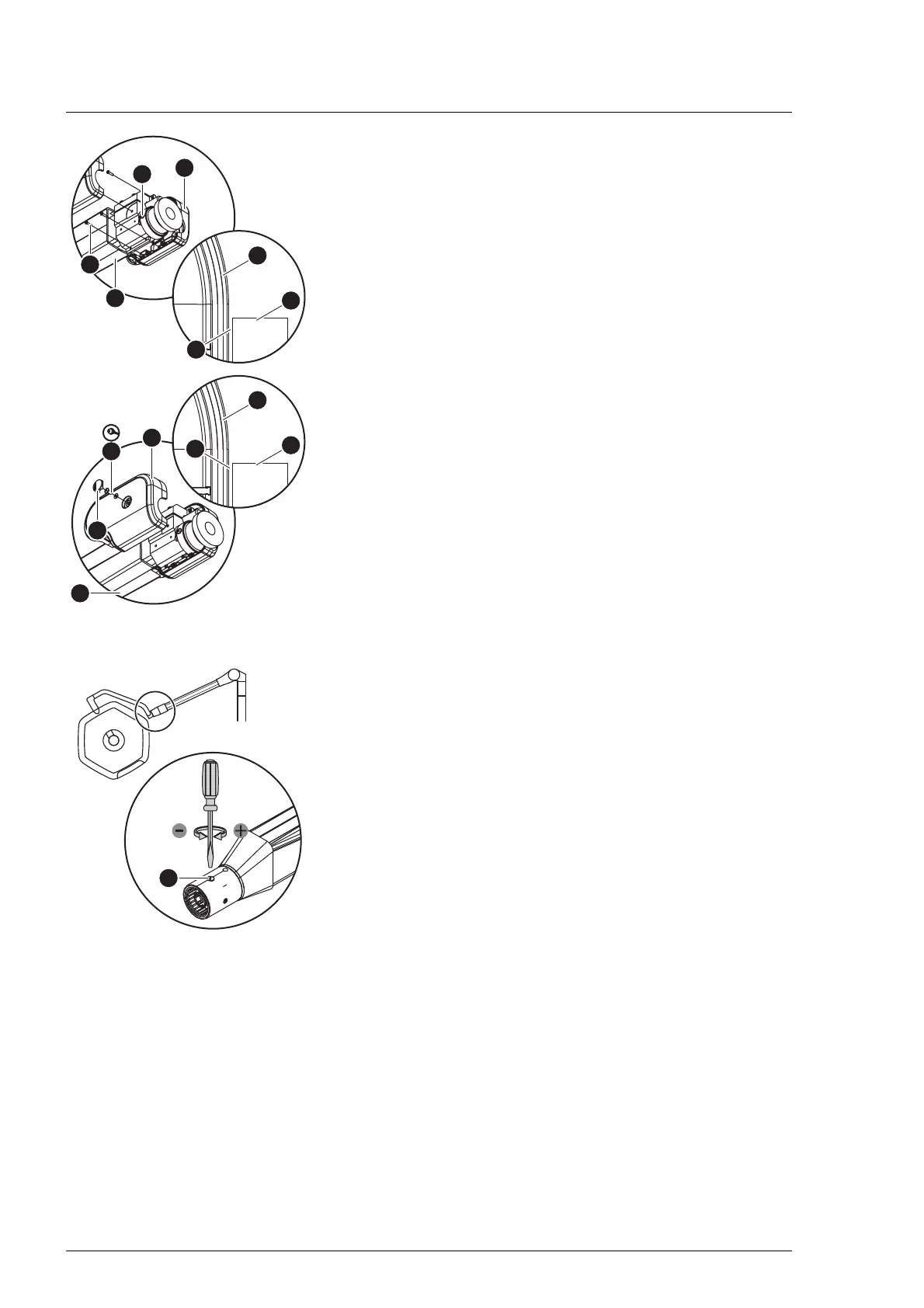
8. Mount the front cover on the spring arm [9].
a) Position the right front cover [D] on the spring arm so that
there is a gap [K] between the connecting pin of the
adaptation [J] and the cover.
b) Attach the right front cover to the spring arm with 3 PT
screws [E] (Torx T10 screwdriver).
c) Position the left front cover [A] on the spring arm so that
there is a gap between the connecting pin of the
adaptation and the cover and so that, at the joint between
the two front cover panels, all catches slide into one
another and engage.
d) Fasten the left front cover with 1 MLF screw and its washer
[C] (Torx T10 torque screwdriver with a torque of 1 Nm/
0.73 ft lb) on the spring arm.
e) Insert 1 PUSH-button [B] flush into the left front cover. The
PUSH-button may not protrude from the cover.
5.15.3 AC 2000 NRH mobil spring arm
1. Switch off the surgical light at a control module and
disconnect it from the mains power (see Chapter 5.7).
2. Use a suitable Phillips screwdriver to remove the locking
screw on the retaining sleeve.
3. Turn the retaining sleeve until the brake screw becomes
visible on the bottom.
4. Adjust the brake [A] with a suitable flathead screwdriver.
– Increase the braking force:
Turn the flathead screwdriver clockwise.
– Reduce the brake force:
Turn the flathead screwdriver in an anticlockwise direction.
5. Test the braking strength. The surgical light must be easy to
adjust and remain steadily in the set swivel position.
6. Rotate the retaining sleeve back into the original mounting
position and secure it with the locking screw.
5.16 Adjusting the brake force on the surgical light
The braking force should only be set by personnel who have been
trained by Baxter in this work.
1. Switch off the surgical light at a control module and
disconnect it from the mains power (see Chapter 5.7).