Use
56
7990087_030_03 – 2080492 – 2023-01-19
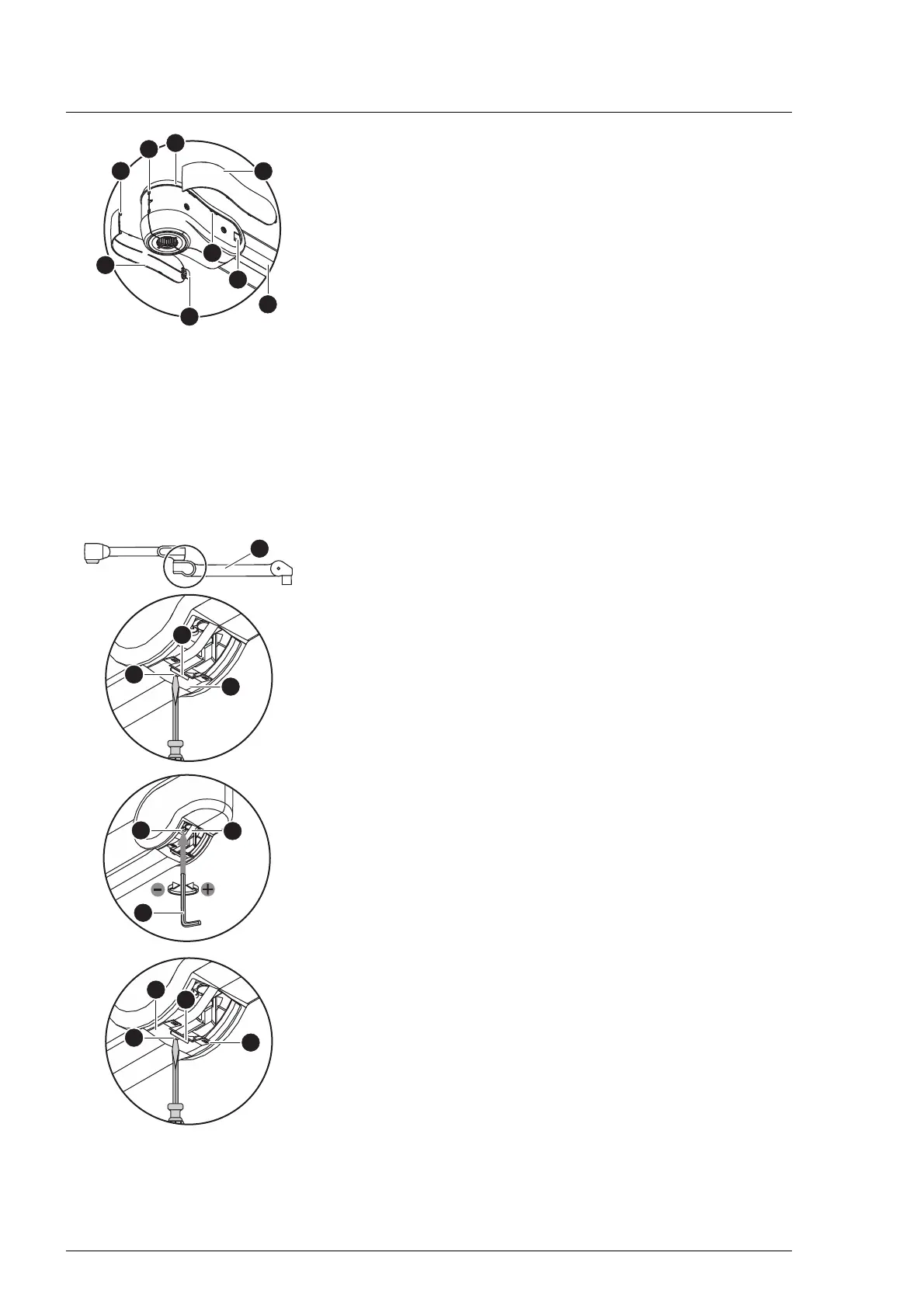
8. Install the decor caps [A] of the socket cover [B].
a) Insert the right and left decor cap flush with the socket
cover into the mounts [F], using light pressure.
b) Push the lugs [C] of the decor caps into the recesses [D] of
the socket cover and the locking mechanisms [E] into the
mounts [K] until they engage.
9. Check the secure fit of the decor caps in the socket cover on
the boom.
– The decor caps must be connected to the socket cover
with the least possible gap.
5.13 Setting the spring force of the spring arm
The spring force should only be set by personnel who have been
trained by Baxter in this work.
During adjustment work, make sure that any electrical cables in
the spring arm remain routed in the center of the spring arm and
do not slip underneath other components.
5.13.1 L21, LCH19 spring arm
1. Switch off the surgical light at a control module and
disconnect it from the mains power (see Chapter 5.7).
2. Open the lower faceplate [A].
a) Insert a suitable flathead screwdriver into the opening [B].
b) Slightly press the flathead screwdriver upwards and guide
the locking hook [C] out of the rear spring arm cover.
c) Push the faceplate towards the rear back into the side
cover with the slot screwdriver.
3. Swivel the spring arm [7] 5 to 10 degrees upwards.
The adjustment screw of the spring arm is relieved.
4. Carefully move any electrical cables [D] to the side and insert
a Size 5 Allen key [E] into the adjustment opening [F].
5. Adjust the spring force.
– If the spring arm drops, increase the spring force:
Turn the Allen key in an anticlockwise direction.
– If the spring arm rises, decrease the spring force:
Turn the Allen key clockwise.
6. Test the spring strength. The support arm must remain stable
in the set height position.
7. Close the lower faceplate [A].
a) Manually pull the faceplate out of the side cover and insert
the 2 catches [K] into the rear spring arm cover.
b) Insert the flathead screwdriver into the opening [B],
slightly press the faceplate upwards and guide the locking
hook [C] into the rear spring arm cover.
8. Move the spring arm upwards and downwards. Check the
secure fit of the upper and lower faceplate while doing so.
– The locking hooks must engage with the rear spring arm
cover.
– The plates must slide easily in the lateral guides.