Use
7990087_030_03 – 2080492 – 2023-01-19 53
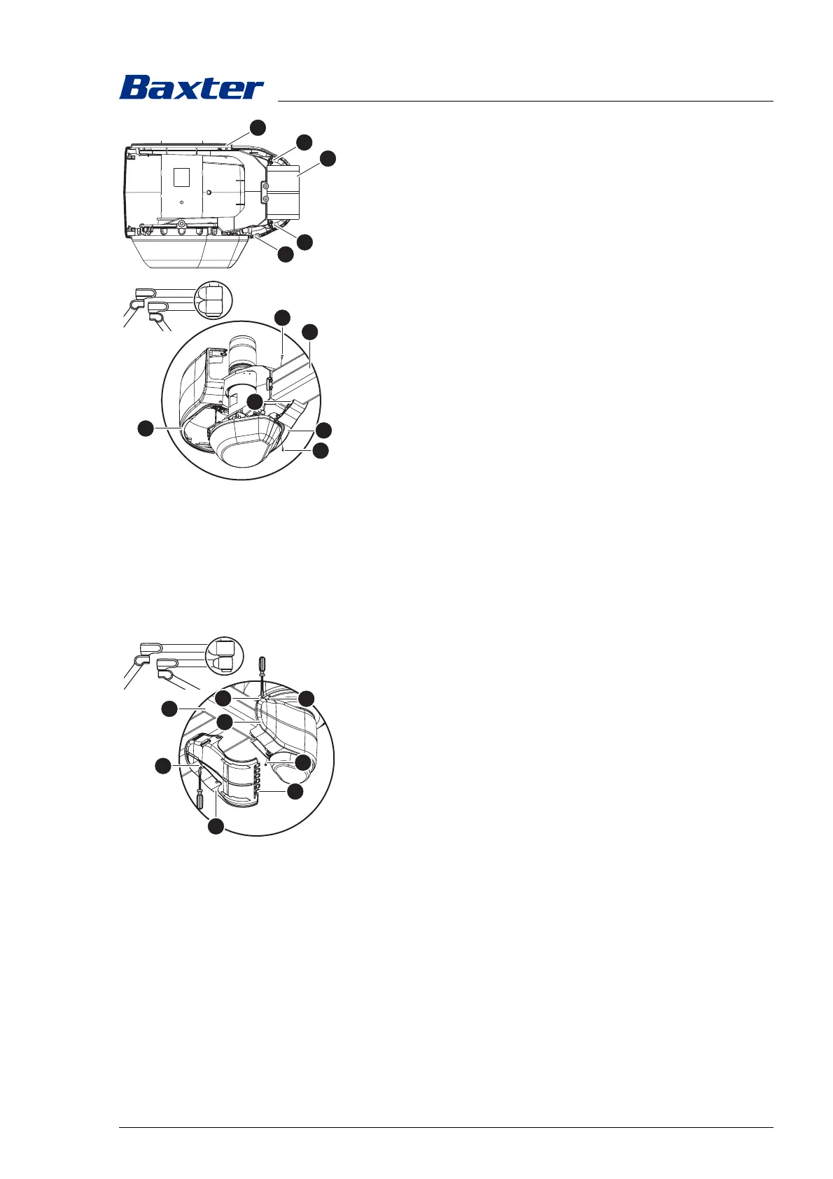
6. Install the right rear cover [E] on the boom [4].
a) Position the right rear cover on the boom so that the
upper cover [H] is inside the rear cover.
b) Attach the right rear cover at the top and bottom to the
boom with a PT screw [F] (Torx T10 screwdriver).
7. Install the left rear cover [A] on the boom [4].
a) Turn the boom so that the hole for the upper PT screw [B]
is accessible.
b) At the joint between the two rear cover panels [A] and [E],
insert the left cover into the catches [I] of the right cover
and close it as if it was fitted on a hinge.
c) Attach the left rear cover at the top and bottom to the
boom with a PT screw [F] (Torx T10 screwdriver).
8. If necessary, install the rear cover of the boom above it.
9. Check the secure fit of the rear cover on the boom.
– The covers on the boom must be connected to one another
with the least possible gap.
– The PT screws must be completely screwed in and may not
protrude from the cover.
5.12.2 S boom
There are 2 opposing brake screws on each boom.
1. Switch off the surgical light at a control module and
disconnect it from the mains power (see Chapter 5.7).
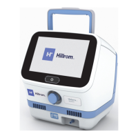
2. Remove the left back cover [A] from the boom [4].
a) Turn the boom so that the upper PT screw [B] is
accessible.
For better access to the PT screw, remove the rear cover
of the boom above it.
b) Using a Torx T10 screwdriver, remove the upper and lower
PT screw [B] on the left rear cover.
c) Insert a suitable flathead screwdriver into the mounting
opening [C] of the left rear cover.
d) Press the flathead screwdriver slightly upwards and
release the cover.
e) Insert the flathead screwdriver into the mounting opening
[D] of the right rear cover [E].
f) Press the flathead screwdriver slightly downwards and
release the cover.
g) Carefully release the catches [F] of the left rear panel at
the joint between the two cover panels.
h) Remove the left rear cover from the boom.