BAL2185_Grease_lubrication_pump_PICO_with_PICO-troniX1_-tronic_0519EN 10158410
...a product of
© BEKA 201 All !9 rights reserved
24
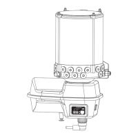
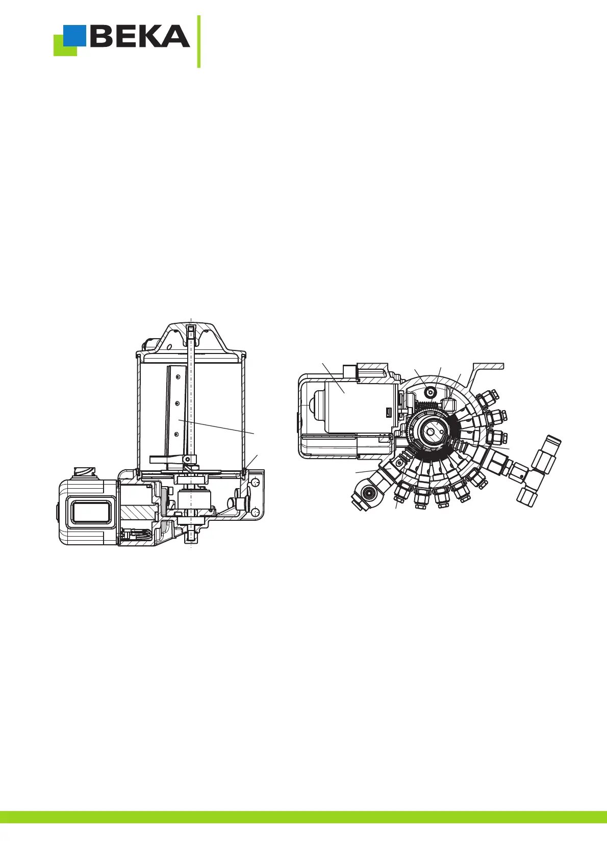
8.3.2 Functionaldescription ofthe versionwith agitatorblade
Thefollowing listedpositions canbe foundin fig.22.
A DC motor optionally with 12 or 24 V DC (pos. 1) drives the eccentric shaft (pos. 3) via a worm drive (pos. 2). The,,
delivery pistons (pos. 4) of the integrated pump elements are pushed into the pump element body (pos. 5) by the rotary
movement and the eccentricity of the shaft (= delivery stroke). The delivery pistons return into their initial position by the
compressionsprings (pos.6) andsuck newlubricant fromthe reservoir(=suction stroke).
Non-return valvesare integrated in thepump elements which preventthat lubricant, which hasalready been displaced, is
sucked back.An agitator blade (pos. 8), which is firmly connected with the eccentric shaft, is located above the centering
ring(pos. 7),which isused asgrease strainer. Theagitatorblade pushesthe lubricanttowards thepump elements.
The device can be filled via a cone-type zerk which is located in the pump housing. In order to avoid an overfilling of the
device,a pressurelimiting valve(pos. 9)is integratedin thepumphousing whichis usedas overfillprotection.
Referto chapter7.2 „Fillingwith lubricant“for furtherinformation onfilling thedevice.
Fig.22:
8.4 Pumpelements
Two different construction types of pump elements can be installed into the device, depending on for which lubrication
systemor forwhich lubricationsystem combinationthe deviceis used.
1
2
3
4
5
6
7
8
9
 Loading...