4-17
Method 2:
Tools required:
None.
Connect all the pins of EEG lead wire together, for example, you can connect them to some metal materials. Then check
the EEG module resistance test, if all the leads are green then pass.
Method 3:
Tools required:
Resistance box
Multimeter
1. Connect the EEG module/cable to the EEG simulator and the monitor.
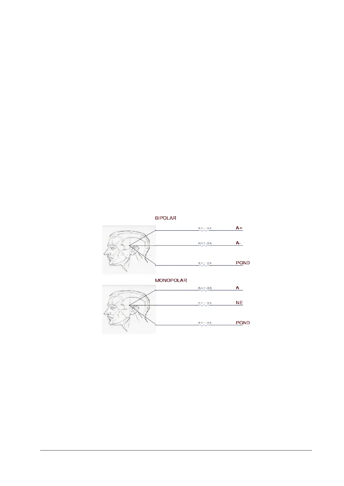
2. Set Montage Type: Bipolar Mode.
3. Adjust the resistance box to 1 kΩ, verify the resistance value displayed on the monitor is 1kΩ.
4. Test the lead type of the monitor to B+, C+ and D+ respectively instead of lead A+.
5. Set Montage Type: Monopolar Mode , then repeat the step 3~4.
EEG Module (Self-made Module)
You can perform the test by any one of the following methods:
Method 1:
Test tools: ECG simulator that supports sine wave output
1. Connect the EEG lead to the ECG simulator.
Configure the ECG simulator as follows: output of sine wave, output frequency of 0.5–30Hz, and output amplitude
of 2mV. Connect the EEG's PGND lead to the RL lead interface of the ECG simulator, the EEG's EEG1+ lead to the LA
lead interface of the ECG simulator, and other EEG leads to random interfaces of the ECG simulator.