4-18
2. On the EEG menu of the monitor, set the EEG input range to 2000uV. If a sine wave is displayed int he EEG
waveform area on the monitor screen, the EEG module is functional.
Method 2:
Test tools: None
Connect all EEG leads together, for example, connect them to the same conducive metal object. Then, in the EEG
module settings on the monitor, select impedance test. The electrode impedance is displayed. If the impedance of
all leads is 0 or 1, the EEG module is functional.
Method 3:
Test tools:
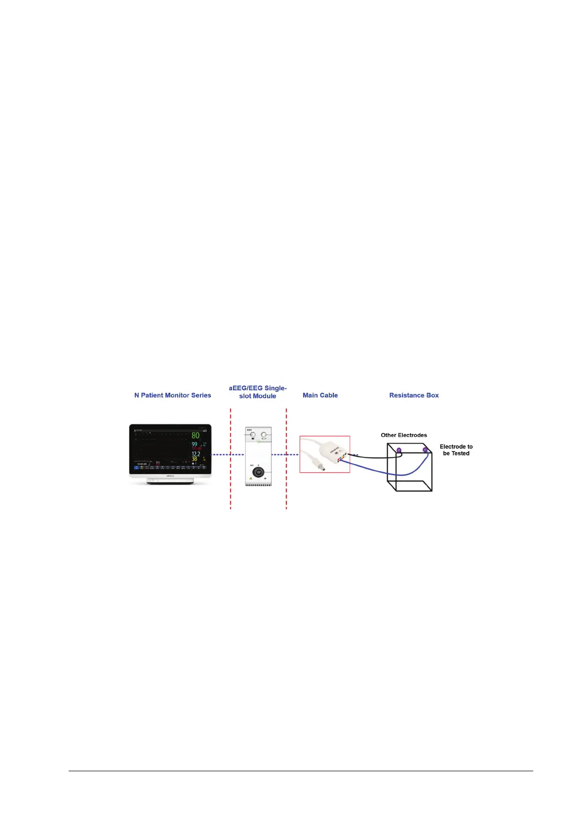
Resistance box
1. Connect the EEG module/cable, ECG simulator and monitor. Connect the electrode to be tested to one end of the
resistance box, and other electrodes to the other end of the resistance box.
2. Set Montage mode to Bi-Polar.
3. Set the resistance box impedance to 5kΩ. Check whether the impedance displayed on the monitor is 5±1kΩ.
4. Test EEG1+, EEG2+, EEG3+ and EEG4+ respectively.
5. Set Montage mode to Uni-Polar. Repeat steps 3 and 4.
4.4.12 BIS Test
You can choose either of the following methods to perform the test:
Method 1:
Tools required:
None.
1. Connect the BIS sensor to a healthy, wide-awake adult as directed in the Operator's Manual.
2. Check the EEG wave and BIS numerics displayed on the screen and make sure the BIS value is within 80 and 100.
Method 2:
Tools required: