4-16
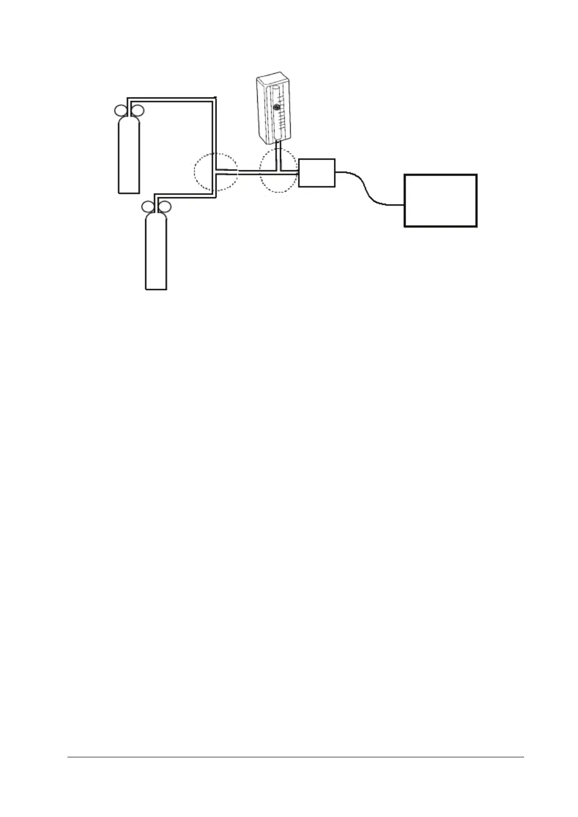
6. Turn on the relief valves of N
2
gas cylinder and CO
2
cylinder respectively to ensure that only one gas cylinder is
connected to the T-shape connector at a time.
7. Adjust the relief valves respectively to ensure a stable flow by maintaining the reading on the flowmeter at a value
between 2 and 5 L/min.
8. Switch between the two cylinders to connect Mainstream CO
2
sensor at intervals of 6 -10s and check if the
displayed CO
2
value is 45±2 mmHg.
4.4.9 Sidestream and Microstream CO
2
Tests
See section 4.2.3Sidestream and Microstream CO2 Tests.
4.4.10 AG Tests
See section 4.2.4AG Tests.
4.4.11 EEG Test
You can choose either of the following methods to perform the test:
Method 1:
Tools required:
ECG simulator with Sine wave output function.
1. Connect pins of EEG lead wires to an ECG simulator.
Set the ECG simulator to output Sine wave and frequency to between 0.5 and 30Hz. The range is 2mV. The GND pin
of EEG module connects to RL of ECG simulator. The A+ pin of EEG module connects to LA of ECG simulator. The
other pins of EEG lead wires connect to any ECG lead as you wish.
2. Open the EEG setting menu on monitor, Set the Scale of EEG to be 2000uV. Then you can find a Sine wave on
screen of Patient Monitor.
Relief valve
T-shape
connector
N
2
gas cylinder
Relief valve
Mainstream sensor probe
T-shape connector
CO
2
gas cylinder
Monitor
Flowmeter