7-7
7.4 Further Disassembly of the Front Case Assembly
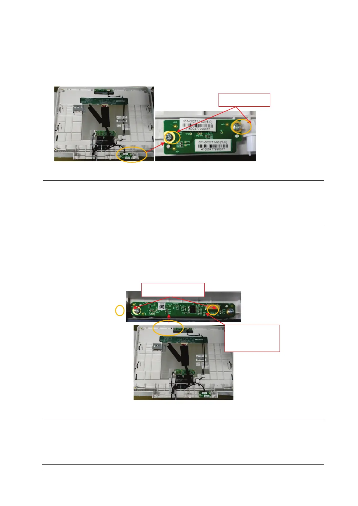
7.4.1 Removing the PowerSwitch Board
1. Remove the connection line on the powerswitch board.
2. Remove the two PT3×8 screws and take out the powerswitch board.
Use proper force to remove the cable carefully lest it would be broken.
During installation, press the board to the silicone keypad direction by aligning with the front case board
positioning rib.
Note to control the torsion when tightening the twoPT3×8 screws again, avoiding screw sliding.
7.4.2 Removing the Alarm Lamp and Light Sensor Board
1. Remove the connection line on the alarm lamp and light sensor board.
2. Remove the two PT3×8 screws and take out the alarm lamp and light sensor board.
Use proper force to remove the cable carefully lest it would be broken.
During installation, press the board to the alarm lamp shade direction by aligning with the front case
board positioning rib.
Note to control the torsion when tightening the two PT3×8 screws again, avoiding screw sliding.
2PCS
2PCS
Connection line
socket