BERNINA International AG Seestrasse 161 CH-8266 Steckborn Schweiz Seite 45 von 172
DRAFT – VERSION
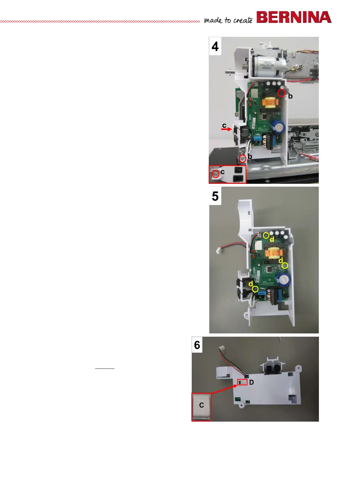
• Picture 4 - Remove 2 fastening screws b (T20 M4X10).
• Remove shoulder screw c. Pull out the power supply unit
housing along with PCBA-Power Supply Unit.
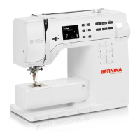
• Picture 5 - Remove 3 fastening screws d (T10 M3X8) in
order to remove PCBA-Power Supply Unit from the
housing.
Note:
Since the power supply unit only comes complete with housing
as a spare part, it doesn't really make sense to remove the
PCBA Power Supply Unit from the housing. Plus, the primary
current fuse is built-in and cannot be removed (or replaced).
Note:
In order to improve EMC (Electromagnetic Compatibility), a
conductive fabric gasket is supplied along with the power
supply unit, complete as a replacement kit.
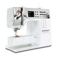
• Picture 6 - Insert conductive fabric gasket C with sticky
side down into opening D. Press slightly.
Assembly:
• Picture 2 - Replug PCBA Power Supply Unit and PCBA-
Base connecting power cable to PCBA-Base. If
necessary, use round side of spring mounting tool
398112.03.0+ as an aid.
• Ensure that the conductive fabric gasket touches the
frame.
• Picture 4 - Attach power supply unit housing to the frame
with screws b and c.
• Picture 3 - Refit protective cover B.
• Picture 1 - Thread drive belt into wheel cover and slide
onto main motor pinion.
• Picture 1 - Turn main motor in such way that the
drive belt is slightly tensioned. Retighten the two
screws a.
• Picture 1 - Refit wheel, sliding it onto pinion.
• Refit the covers (see 4.1
).
Note:
Test run the machine after refitting the front cover.