BERNINA International AG Seestrasse 161 CH-8266 Steckborn Schweiz Seite 47 von 172
DRAFT – VERSION
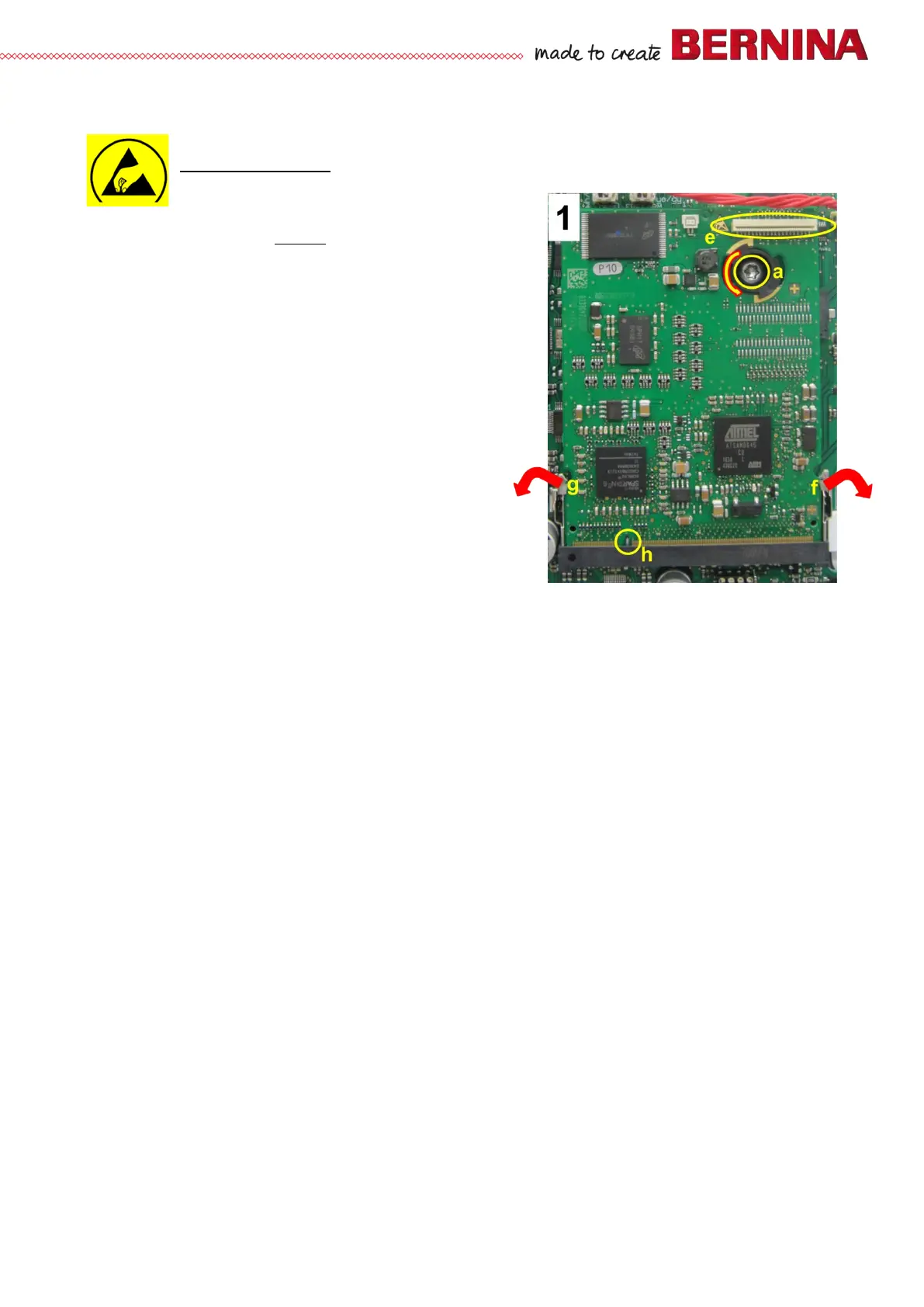
4.2.3 PCBA-CPU-Module (ARM9)
See ESD-related note
Disassembly:
• Remove the covers (see 4.1
)
• Picture 1 - Screen wire is removed from slot e.
• Picture 1 - Remove screw a.
• Picture 1 - Pull latchings f and g outward at the same
time. PCBA-CPU-Module (ARM9) will then come off to
front.
• Picture 1 - Disconnect PCBA-CPU-Module (ARM9).
• Picture 1 - Turn spacer counterclockwise. Then remove.
Assembly:
• Picture 1 - Turn spacer in clockwise.
• Picture 1 - Reconnect PCBA-CPU-Module (ARM9),
taking care of coding h.
• Picture 1 - Push PCBA-CPU-Module (ARM9) down
until latchings f and g engage.
• Picture 1 - Refit and retighten screw a.
Note:
On fitting a new or repaired PCBA-CPU-Module (ARM9), it is necessary to load the required firmware for the
respective model.