BERNINA International AG Seestrasse 161 CH-8266 Steckborn Schweiz Seite 54 von 172
DRAFT – VERSION
4.2.10 Sensor support ABC (presser foot recognition)
See ESD-related note
Disassembly:
• Remove the covers (see 4.1
)
• Move needle bar to upper dead center. Remove
needle.
• Remove take-up lever cover. (see 4.4.12
).
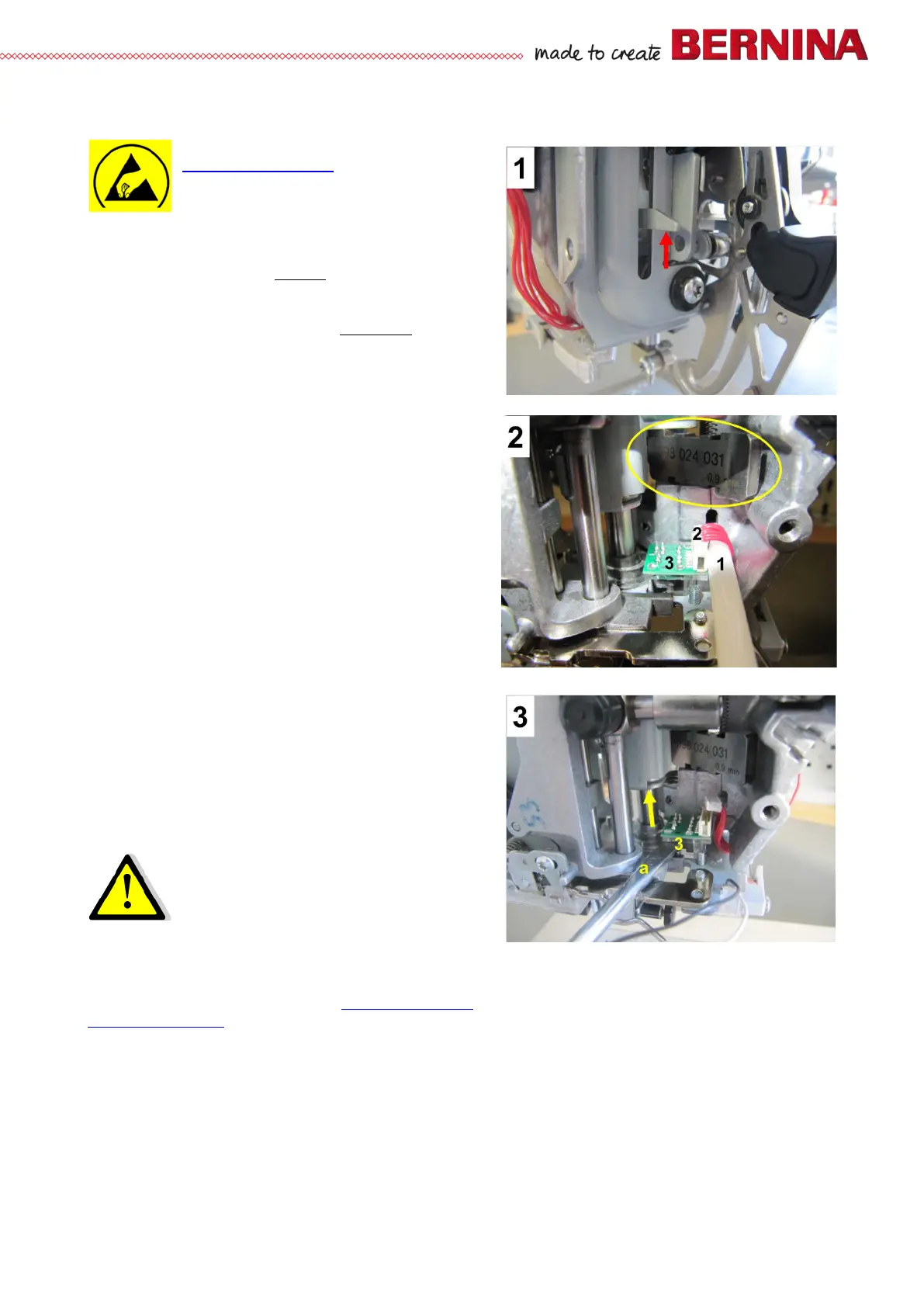
• Picture 1 - Move presser-foot bar to highest
position by hand.
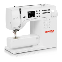
• Picture 2 - Lock presser-foot bar in highest position
using the feed-dog height gauge (398024.03.1).
Unplug connector 2 from ABC sensor 3 using plug
ram 1 (031935.50.00).
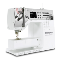
• Picture 3 - Use screwdriver a to lift sensor support
3 over spherical bearing in direction of arrow as
indicated.
• Turn sensor support slightly to front, then slide it
off presser-foot bar to right.
Assembly:
• Bring ABC sensor support over needle bar. Then
push it down carefully over spherical bearing and
into correct position.
• Use plug ram to reconnect ABC sensor and
PCBA-Base.
• Picture 1 - Mover presser-foot bar slightly up by
hand.
• Picture 2 - Remove feed-dog height gauge. Lower
presser-foot bar.
• Refit thread take-up lever cover.
• Insert a new needle.
• Refit covers (if appropriate).
Caution: Risk of Breakage!
Take care that sensor support 3 doesn't
catch edges while fitting it.
Note:
Check ABC sensor for functioning in Service Program 4l
. Calibrate buttonhole foot with slide 3A in
Service Program 6c.



 To Next Page