BERNINA International AG Seestrasse 161 CH-8266 Steckborn Schweiz Seite 52 von 172
DRAFT – VERSION
4.2.8 PCBA-RET (B 590, B 570 QE, B 540, B 520 & B 500 Embroidery Only)
See ESD-related note
Disassembly:
• Remove the covers (see 4.1
)
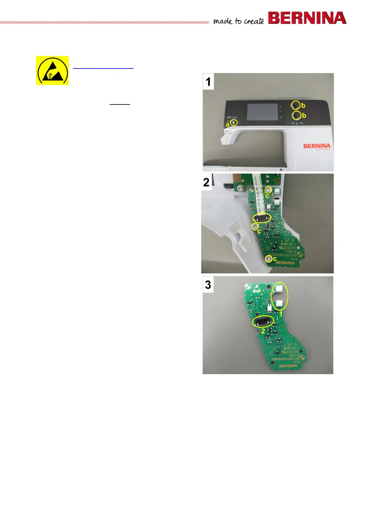
• Picture 1 - Remove SSU slide and knobs.
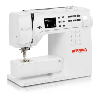
• Picture 2 - Disconnect PCBA-RET flat ribbon
cable.
• Picture 2 - Remove three screws c T10 (3x8).
• Lift PCBA-RET off.
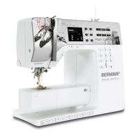
• Picture 3 - Upper-thread sensor light barrier 1.
• Picture 3 - PCBA-Front cover flat ribbon cable
connector 2.
Assembly:
• Position PCBA-RET properly, taking care not to
jam the flat ribbon cable.
• Picture 2 - Refit PCBA-RET with three screws c.
• Picture 2 - Reconnect PCBA-RET flat ribbon
cable.