BERNINA International AG Seestrasse 161 CH-8266 Steckborn Schweiz Seite 67 von 172
DRAFT – VERSION
4.3.5 Base shaft
See ESD-related note
Disassembly:
• Remove the covers (see 4.1
).
• Remove PCBA-Base (see 4.2.4)
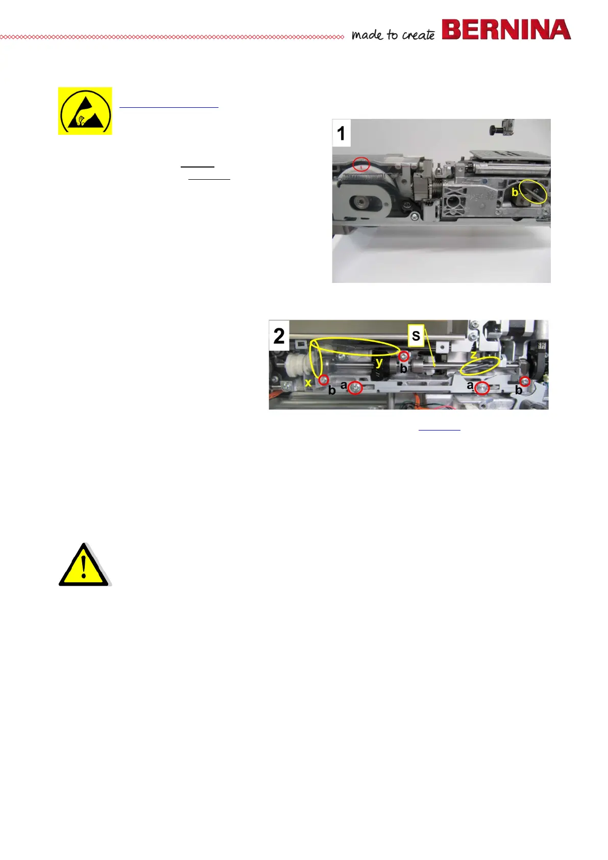
• Picture 1 – Use pinning tool b (007937.50.00) to
pin hook driver (loop lift position), taking care that
the (marked) notch in the white hook drive wheel
matches up with the marking on the base.
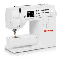
• Picture 2 – Unhook tension springs x, y and z. Put
aside.
• Picture 2 – Remove screws a T20 (M4x10).
Remove feed-dog drop lug.
• Picture 2 – Remove screws b T20 (M4x10)
including clamps.
• Picture 2 – Slide drive belt off base shaft. Lift base shaft out.
Assembly:
• Using loop lift gauge 734571.70.01, lock vertical shaft in loop lift position (see 5.5.3
).
• Picture 2 – Slide base shaft in drive belt, so that base shaft can be locked.
• Picture 2 – Refit clamps and screws b first.
• Picture 2 – Refit shaft support in the centre, fastening it with screw b with a distance to the base shaft
of 0.1mm.
• Picture 2 – Refit feed-dog drop lug, and refit and retighten screws a.
• Picture 2 – Rehook tension springs x, y, and z. Check for proper fitting.
Note:
It is important to check base shaft for correct functioning of timing, loop lift, thread cutting etc.
Adjust if necessary.