BERNINA International AG Seestrasse 161 CH-8266 Steckborn Schweiz Seite 49 von 172
DRAFT – VERSION
4.2.5 PCBA-Position Hall
See ESD-related note
Disassembly:
• Remove the covers (see 4.1
)
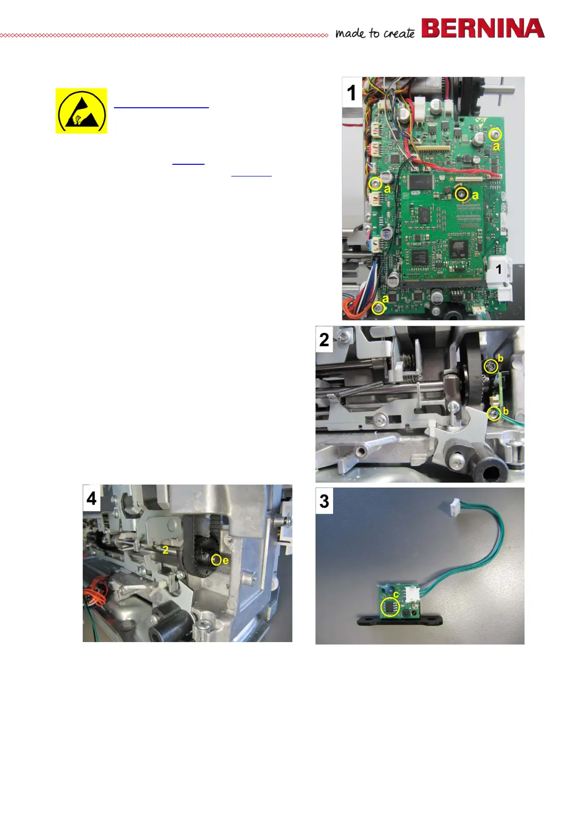
• Picture 1 – Remove PCBA-Base (see 4.2.4).
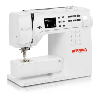
• Picture 2 - Remove screws b and PCBA-Position Hall.
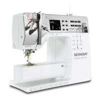
• Picture 3 - PCB with black mounting plate and Hall
sensor c.
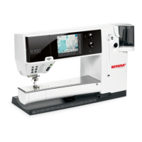
• Picture 4 - The magnetic encoder e for the Hall sensor c
sits at the end of base shaft 2.
Assembly:
• Picture 2 - Position PCBA-Position Hall and fasten with
screws b.
• Picture 1 - Hook feed-dog drop 1 in behind PCBA-Base.
Position the whole unit and fasten with four screws
a.
• Picture 1 - Reconnect all plugs.
• Refit all covers (if appropriate).