BERNINA International AG Seestrasse 161 CH-8266 Steckborn Schweiz Seite 95 von 172
DRAFT – VERSION
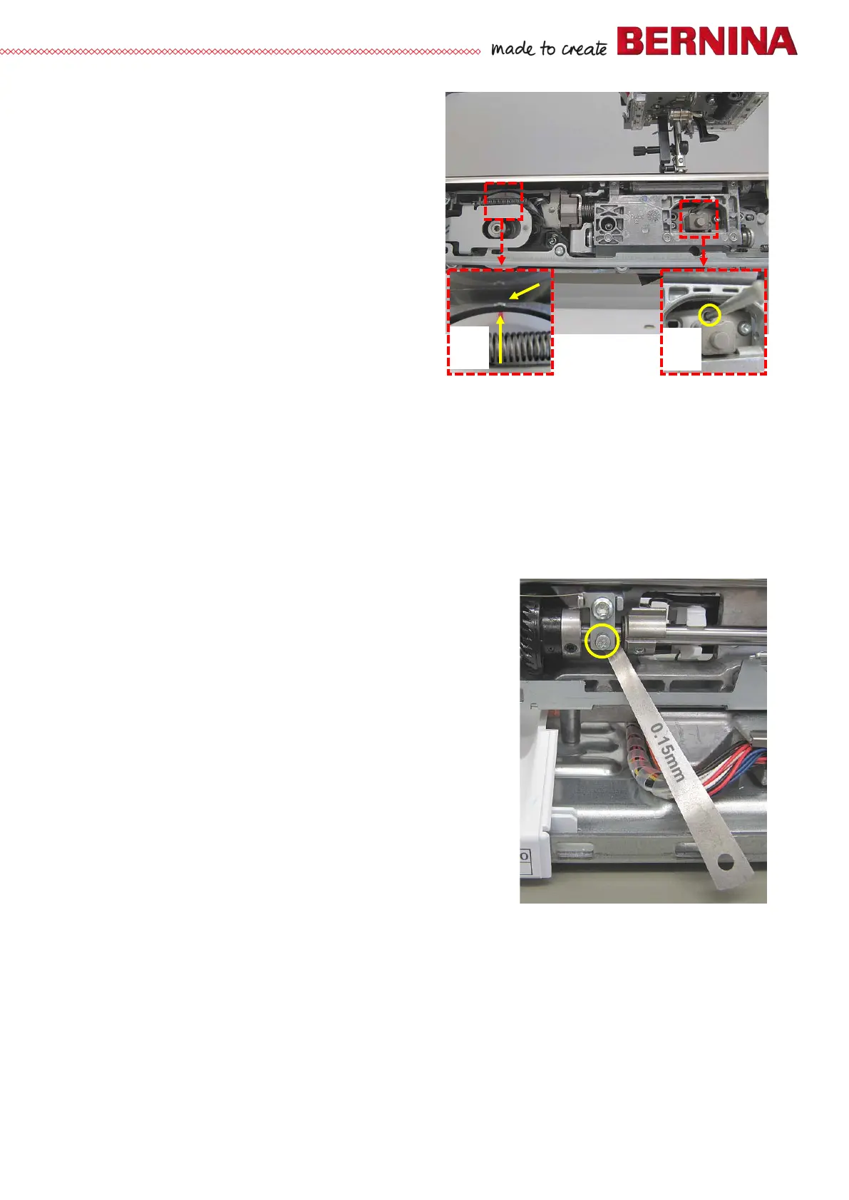
E
F
f
• Rear view - Marking on belt edge must exactly
match marking on base (pict. E). At the same
time, hook driver must be pinnable using pinning
tool 0079937.50.00 (pict. F).
Main shaft / base shaft adjustment
• Remove pinning tool 007937.50.00 from base
shaft (pict. C).
• Untighten second setscrew d2 (T10) on main
shaft belt pulley in direction of rotation (pict. D).
• Use new loop lift gauge 734571.70.01 to set
loop lift (2.618mm).
• Untighten first setscrew d1 (T10) on belt pulley.
• Turn belt pulley until base shaft can be pinned
against lift cam with the 3.0mm pinning tool
007937.50.00 (pict. C).
• Retighten first setscrew d1 (T10) on belt pulley
in direction of rotation.
• Remove gauges.
• Retighten second setscrew d2 (T10) on belt pulley.
Base shaft / belt pulley adjustment
• Check fitting position of belt pulley.
• Check fitting of hook driver (see 4.4.1).
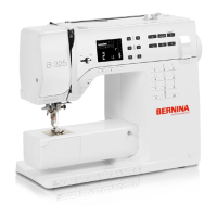
5.5.2 Base shaft-/load lock screw distance
Check:
• Measure distance between base hsaft and load lock screw
with a feeler gauge.
• The distance should be 0.15mm.
Adjustment:
• Turn screw f (T10) to set 0.15mm distance between base
shaft and load lock.