BERNINA International AG Seestrasse 161 CH-8266 Steckborn Schweiz Seite 64 von 172
DRAFT – VERSION
Assembly of blade:
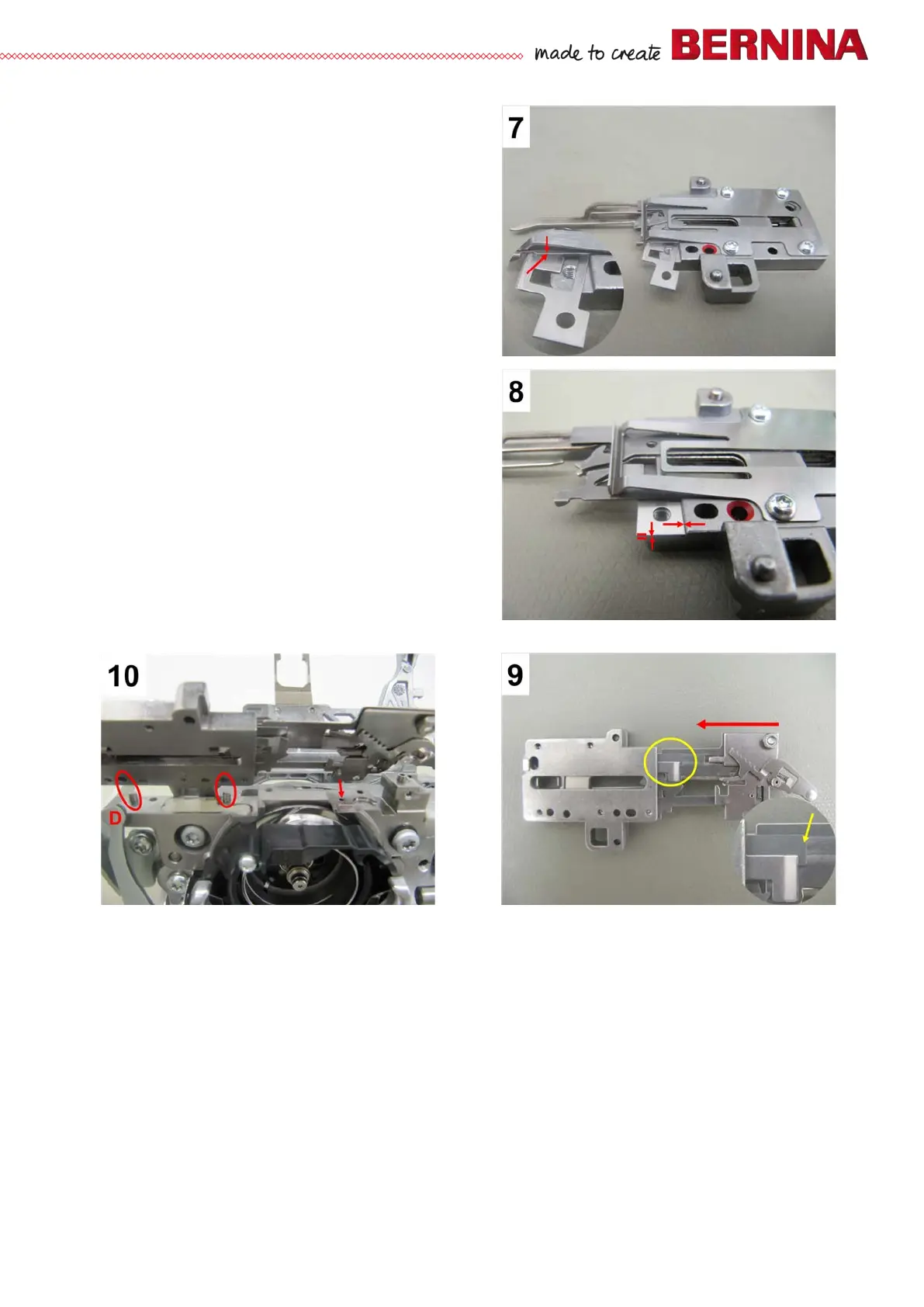
• Picture 7 – Position the new blade under the first
layer of metal sheeting.
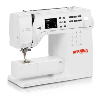
• Picture 8 – The edge of the blade's fastening lug
MUST butt against the recessed edge..
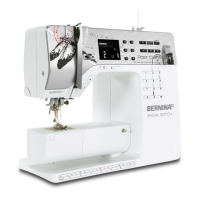
• Picture 5 – Refit and retighten blade securing
screw d (T8).
Assembly of thread-cutting unit:
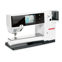
• Picture 9 - Refit the left part of the thread cutter
unit. Insert it from the left and link it with the right
part, ensuring that the thread catcher stands over
the metal plate of the right part (pict. 3.3.2a).
• The left part of the thread catcher/thread cutter unit
must lie flat on the hook race ring to ensure that
the locating pins on the hook race ring mesh
correctly and the thread catcher actuating lever sits
correctly in the opening provided.
• Fasten the left part of the thread-cutting unit with 3
screws 1 (3xT8).
Note regarding servicing:
• When servicing the machine, the thread cutter must always be removed for cleaning purposes.
• The blade is a wear part and therefore available as an individual part.