11.6 Parameter Locking with Jumper J3
There may be the need, with the internal and external dose rate
probe, to protect certain parameters from being changed by
means of a hardware interlock, e.g. calibration factor, back-
ground, dead time. Jumper J3 can be used for this purpose. If
this jumper is closed, the necessary parameters cannot be
changed via the keyboard nor via the interfaces. Normally, the
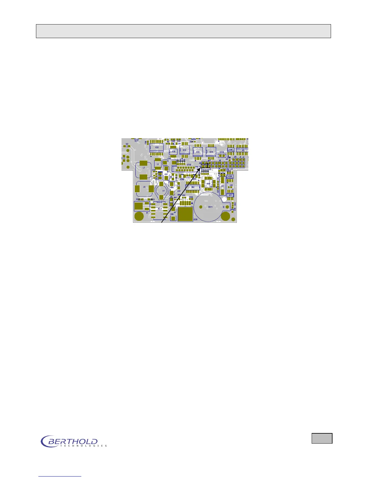
jumper is open. The following PCB layout of the processor
board shows the position of jumper J3.
Figure 11.1: Position of jumper J3
11.7 Pin Assignment of the Fischer Sockets
11 pin Fischer socket: external probe
Pin number Meaning
1 Counting pulse 1, differential input 1 A
2 Counting pulse 2, differential input 2 A
3 Ground
4 + 5V output for probes
5 SDA for EEPROM in probes
6 Control voltage for the HV of probes
7 Code input resistance
8 SCL for EEPROM in probes
9 differential input 1 B
10 differential input 2 B
11 Control input normal - differential count-
ing signal (0 volts = differential input,
open = normal counting signal, TTL)