KBF P + KBF LQC + KBWF (E6) 11/2016 page 148/189
21.4 Analog outputs for temperature and humidity (option)
With this option the chamber is equipped with analog outputs 4-20 mA for temperature and humidity.
These outputs allow transmitting data to external data registration systems or devices.
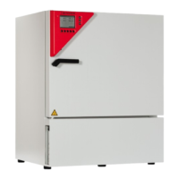
The connection is realized as a DIN socket (3) in the right lateral control panel as follows:
PIN 1: Temperature –
PIN 2: Temperature +
PIN 3: Humidity –
PIN 4: Humidity +
Temperature range: -10 °C / 14 °F to +100 °C / 212 °F
Humidity range: 0 % r.H. to 100 % r.H.
A suitable DIN plug is enclosed.
Figure 33: Pin allocation of DIN socket (3) for option analog outputs
21.5 Zero-voltage relay alarm outputs for temperature and humidity (option)
The chamber equipment with optional zero-voltage relay outputs for temperature and
humidity (option) permits the transmission of alarms to a central monitoring system.
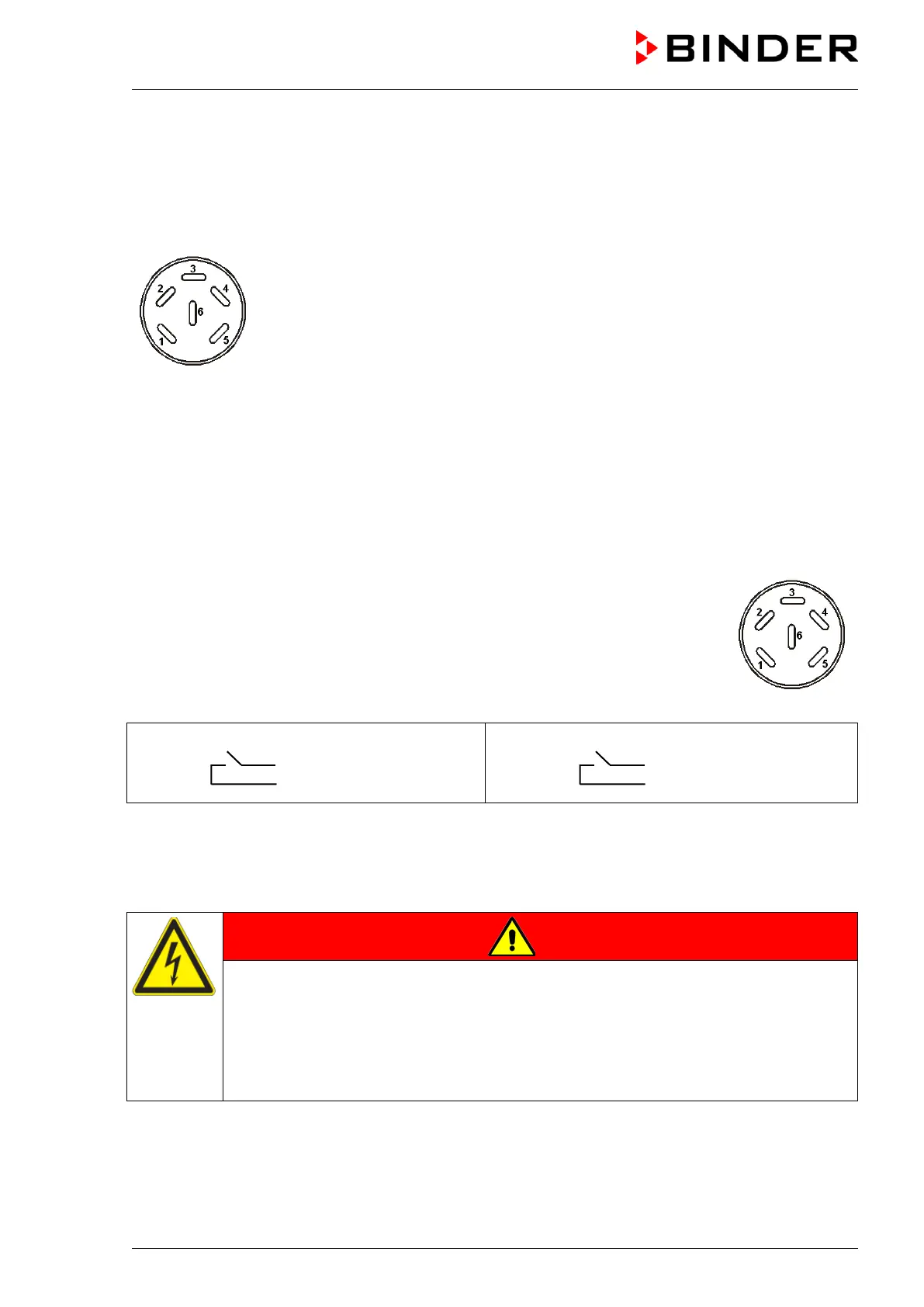
Connection is established via a DIN socket (6) located on the right lateral control pan-
el.
Figure 34: Pin configuration of the DIN socket (6)
Pin 1: Pin
Pin 2: Make
Pin 3: Pol
Pin 4: Make
In case of a temperature alarm, pins 1 and 2 are open; with humidity alarm, pins 3 and 4 are open. This
happens simultaneously with the alarm message shown on the controller display.
In case of power failure, both contacts are open.
Maximum loading capacity of the switching contacts: 24V AC/DC - 2,5A
DANGER
Electrical hazard.
Danger of death.
Damage to switching contacts and connection socket.
∅ Do NOT exceed the maximum switching load of 24V AC/DC – 2.5A.
∅ Do NOT connect any devices with a higher loading capacity.
A temperature and humidity alarm message will remain visible on the controller display during the whole
time of the alarm transmission via the zero-voltage relay outputs.
As soon as the cause of the alarm is rectified, you can reset the alarm transmission via the zero-voltage
relay outputs together with the alarm message on the controller.