KBF P + KBF LQC + KBWF (E6) 11/2016 page 20/189
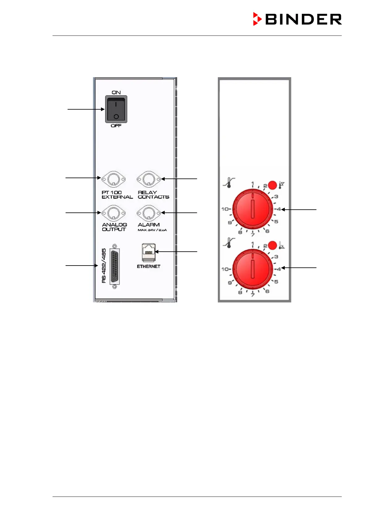
2.4 Lateral control panels
(1)
(2)
(3)
(4)
(5)
(6)
(7)
(8)
(9)
right side left side (optional)
Figure 6: Lateral control panels at the sides of the refrigerating / humidity generation module
with optional equipment
(1) Main power switch
(2) DIN socket for additional Pt 100 sensor (may be available via BINDER INDIVIDUAL customized
solutions)
(3) DIN socket for analog outputs (option)
(4) RS485 interface
(5) DIN socket for switching contacts (may be available via BINDER INDIVIDUAL customized solu-
tions)
(6) DIN socket for zero-voltage relay alarm output (option)
(7) Ethernet interface
(8) Temperature safety device class 3.1 (part of option “Safety device class 3.3”)
(9) Temperature safety device class 3.2 (part of option “Safety device class 3.3”)