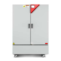
KBF P + KBF LQC + KBWF (E6) 11/2016 page 34/189
When connected to a power supply 1N~ with a frequency of 60 Hz, a leakage current of more than 3.5
mAmp is possible. If grounding through the power cable is insufficient or missing, the leakage current may
flow through the user’s body. Correct installation of the professional grade power socket provided by the
user safely avoids this. Before connecting the chamber to the socket, please check its grounding contact
type plug for appropriate construction and if it is undamaged.
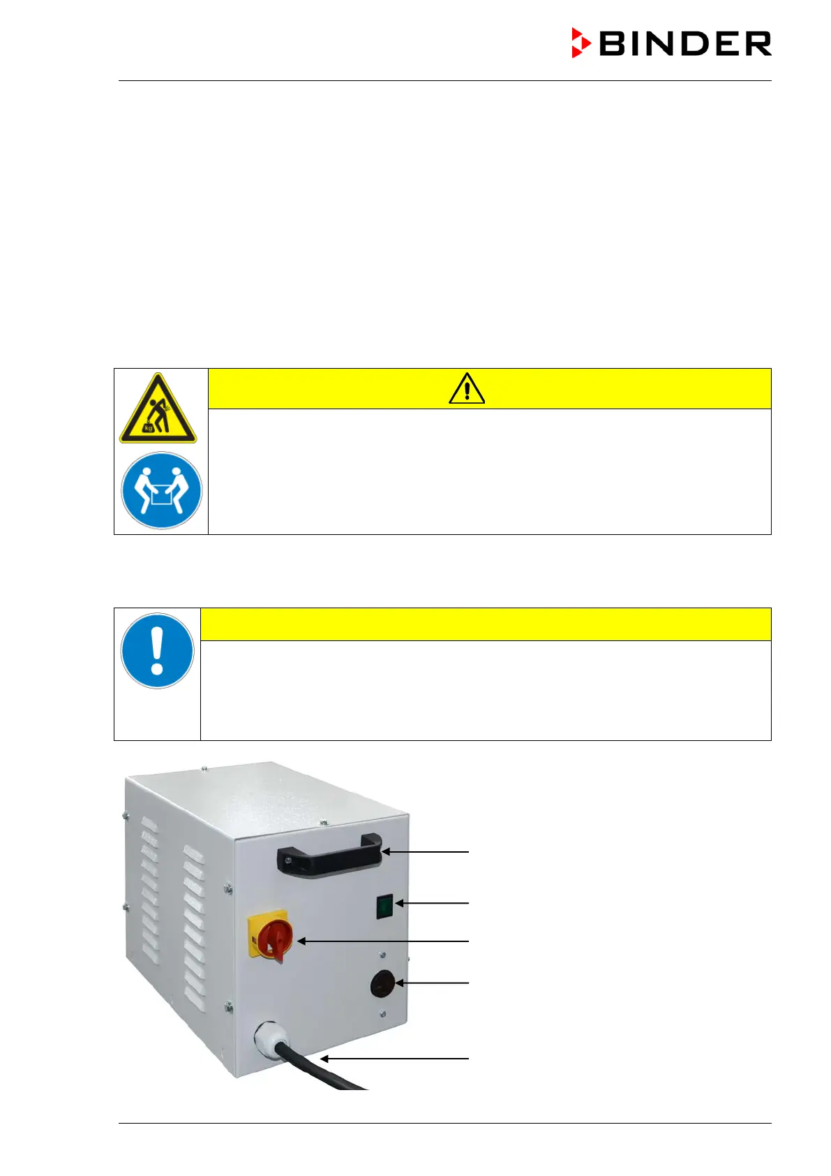
4.7 Connection of the voltage changer (option for KBF P 240 / KBF LQC 240)
The voltage changer enables the constant climate chamber to operate at a power frequency of 115 Volt. It
is packed separately and supplied together with the constant climate chamber.
The voltage changer is supplied with a fixed power connection cable with a NEMA 5-20P plug. It is pro-
tected against excess-current with an internal over-current release category B16A. The connection is
made by the customer.
CAUTION
Sliding or tilting of the voltage changer.
Damage to the voltage changer.
Risk of injury by lifting heavy loads.
Lift the voltage changer at both carrying handles from the pallet with two persons.
Do not install the voltage changer in the exhaust air flow at the rear of the constant climate chamber.
For the installation of the voltage changer next to the constant climate chamber, provide a wall distance of
the constant climate chamber of approx. 0.4 m / 1.3 ft.
CAUTION
Danger of overheating.
Damage to the voltage changer.
∅ Do NOT install the voltage changer in unventilated recesses.
Ensure sufficient ventilation for dispersal of the heat.
(A) Carrying handle
(B) Pilot lamp (green)
(C) Power switch
(D) Connection socket for con-
stant climate chamber
(E) Power cable
Figure 15: Voltage changer (front)
(B)
(C)
(D)
(E)