Data Logger
The data logger can record the output voltage, current, and error codes of all three channels. Log data
can be congured to record either Voltage only, Current only, or both.
Connect a USB ash drive to the front panel USB port. Max. Recording time will vary based on the ash
drive size and the amount of the data being logged.
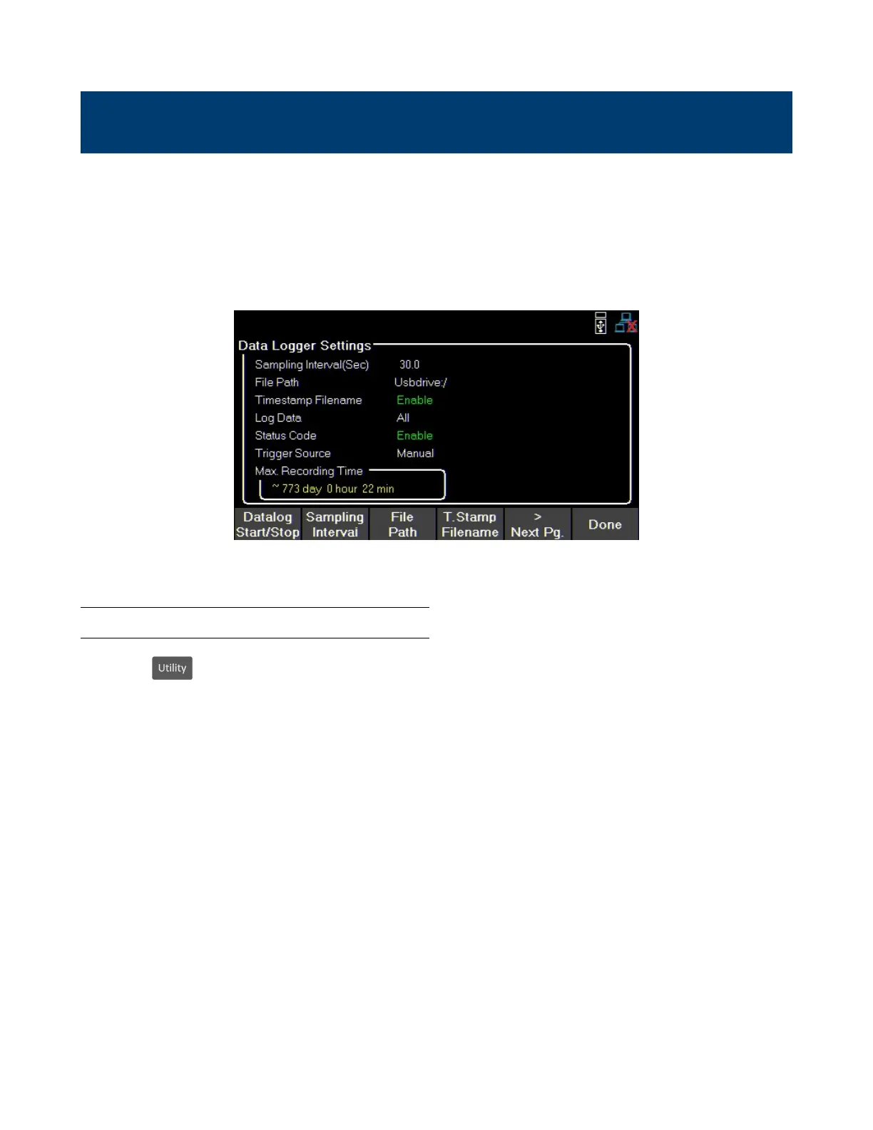
Figure 6.1 Data Logger Max Time
6.1 Using the Data Logger Function
Press the button then use the soft key to select Data logger. The Data Logger settings can be
selected in this menu.
Before starting the Data Logger its settings must be adjusted.
1. Set the desired Sampling Interval See 6.2.1
2. Select a File Path to determine where to store the collected data. see 6.2.2
3. Enable or disable T. Stamp Filename. See 6.2.3
4. Choose what data to record. See 6.2.4
5. Enable or disable Status Code. See 6.2.5
6. Select a Trigger Source. See 6.2.6
7. After setting all desired parameters press datalog Start/Stop to begin recording. Staring data log
will vary based on chosen trigger. See6.2.7
www.GlobalTestSupply.com
Find Quality Products Online at: sales@GlobalTestSupply.com
 Loading...