Operating Instructions ACTIVE06/07 121
06/07 Operating Instructions ACTIVE 121
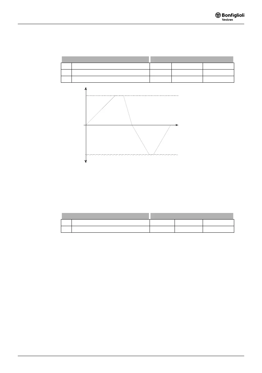
The ramps for
Emergency Stop Clockwise 424 and Emergency Stop Anticlockwise
425 of the drive to be activated via the parameter for stopping behavior
Operation
Mode
630 must be selected according to the application. The non-linear (S-shaped)
course of the ramps is not active in the case of an emergency stop of the drive.
Parameter Settings
No. Description Min. Max. Fact. sett.
424 Emergency Stop Clockwise 0.01 Hz/s 9999.99 Hz/s 5.00 Hz/s
425 Emergency Stop Anticlockwise 0.01 Hz/s 9999.99 Hz/s 5.00 Hz/s
Rotary field
clockwise
Rotary field
ant icloc kw ise
+f
m ax
-f
ma x
t
Acceleration
(Clockwise) 420
Deceleration (Clockwise)
Emerg ency Sto p
or
421
424Clockwise
Acceleration
anticlockwise() 422
Deceler at ion a nt icl ockwi se
Emerg ency Sto p a n ticlo ckwis e
or
423
425
The parameter
Maximum Leading 426 limits the difference between the output of the
ramp and the current actual value of the drive. The set maximum deviation is a dead
time for the control system which should be kept as low as possible.
In case the drive is loaded heavily and high acceleration and deceleration values are
selected it is possible, that a set controller limit is reached while the drive is acceler-
ated or decelerated. In this case, the drive cannot follow the defined acceleration or
deceleration ramps. With
Maximum Leading 426, you can limit the max. leading of
the ramp.
Parameter Settings
No. Description Min. Max. Fact. sett.
426 Maximum Leading 0.01 Hz 999.99 Hz 5.00 Hz
Example: Fixed value at ramp output = 20 Hz, current actual value of drive = 15 Hz,
selected
Maximum Leading 426 = 5 Hz
The frequency at the ramp output is increased to 15 Hz only and it is not increased
further. The difference (leading) between the frequency value at the ramp output and
the current actual frequency of the drive is limited to 5 Hz in this way.
The load occurring in a linear acceleration of the drive is reduced by the adjustable
modification speeds (S curve). The non-linear course of the frequency is defined as a
ramp and states the time range in which the frequency is to be guided to the set ramp.
The values set with parameters 420 to 423 are maintained regardless of the selected
ramp times.

 Loading...


