Operating Instructions ACTIVE 06/07122
122 Operating Instructions ACTIVE 06/07
Setting the ramp time to 0 ms deactivates the function S curve and enables the use of
the linear ramps. The data set change-over of the parameters within an acceleration
phase of the drive demands the defined take-over of the values. The controller calcu-
lates the values required in order to reach the reference value from the ratio of the
acceleration to the ramp time and uses it until the acceleration phase is finished. With
this method, exceeding the reference values is avoided and a data set change-over
between extremely deviating values becomes possible.
Parameter Settings
No. Description Min. Max. Fact. sett.
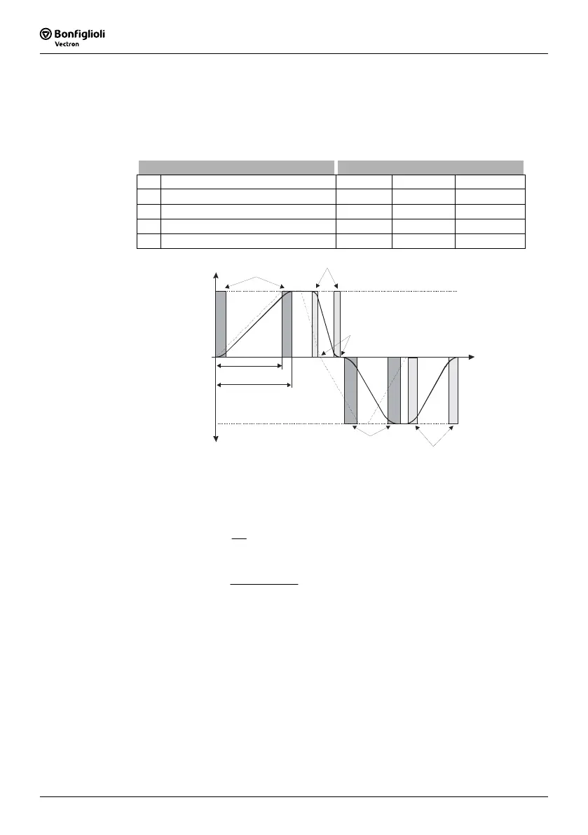
430 Ramp Rise Time Clockwise 0 ms 65000 ms 0 ms
431 Ramp Fall Time Clockwise 0 ms 65000 ms 0 ms
432 Ramp Rise Time Anticlockwise 0 ms 65000 ms 0 ms
433 Ramp Rise Time Anticlockwise 0 ms 65000 ms 0 ms
Rotary field
clock wis e
Rotary field
ant icloc kw ise
+f
m ax
-f
ma x
Ramp Rise Time Clockwise 430
Ram p F all Time Cl ockwi se 431
Ram p R is e Time An ticlo ckwis e 432
Ram p R is e Time An ticlo ckwis e 433
t
t
au fr
t
au f
Frequency reference value = 0.00 Hz
Example: Calculation of the acceleration time in clockwise rotation at an accelera-
tion from 20 Hz to 50 Hz (fmax) and an acceleration ramp of 2 Hz/s for
parameter
Acceleration (Clockwise) 420. The parameter Ramp Rise
Time Clockwise
430 is set to 100 ms.
r
aufr
a
Δf
t =
s 15
Hz/s2
Hz 20Hz 50
t
aufr
=
−
=
s 15.1ms 100s 15t
ttt
auf
Vraufrauf
=+=
+=
t
aufr
∆f
a
r
t
Vr
t
auf
=
=
=
=
=
acceleration time
clockwise rotary field
change of frequency
acceleration ramp
Acceleration
Clockwise
Ramp Rise Time Clockwise
acceleration time +
ramp rise time

 Loading...


