Operating Instructions ACTIVE06/07 141
06/07 Operating Instructions ACTIVE 141
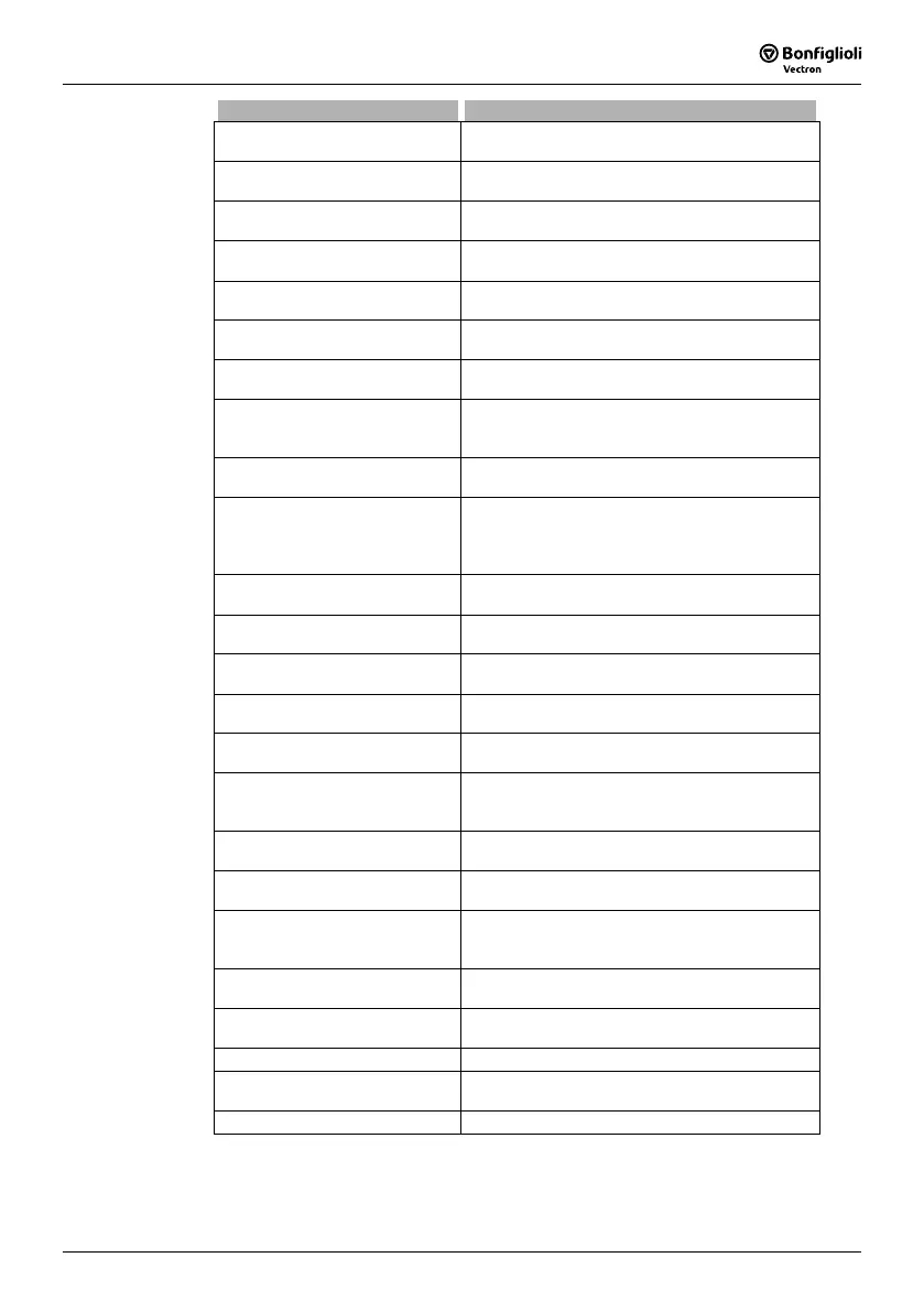
Digital Inputs Function
158 - Timer 1
Output signal of the time function according to
the input connection
Timer 1 83.
159 - Timer 2
Output signal of the time function according to
the input connection
Timer 2 84.
163 -
Reference Frequency
reached
Signal when the
Actual Frequency 241 has
reached the reference frequency.
164 - Setting Frequency
Signal when the
Setting Frequency 510 is smaller
than or equal to the
Actual Frequency 241.
165 - Warning Ixt
The monitoring functions report an overload of
the frequency inverter.
166 -
Warning
Heat sink temperature
Max. heat sink temperature T
K
of 80 °C less the
Warning Limit Heat Sink Temp 407 reached.
167 -
Warning
Inside temperature
Max. inside temperature T
i
of 65 °C less the
Warning Limit Inside Temp. 408 reached.
168 -
Warning
Motor Temperature
Warning behavior according to parameterized
Motor Temp. Operation mode 570 at max. motor
temperature T
PTC
.
169 - General Warning
Signal when
Warnings 269 are displayed with a
critical operating point.
170 - Warning Over temperature
The selected limit values
Warning Limit Heat Sink
Temp.
407, Warning Limit Inside Temp 408 or
the maximum motor temperature have been ex-
ceeded.
171 - Output Comparator 1
The comparison according to the selected
OP.
mode
Comparator 1 540 is true.
172 -
Inverted Output
Comparator 1
Operation mode 171 with inverted logic
(LOW active).
173 - Output Comparator 2
The comparison according to the selected
OP.
mode
Comparator 2 543 is true.
174 -
Inverted Output
Comparator 2
Operation mode 173 with inverted logic
(LOW active).
175 - Digital Signal 1
Signal, according to parameterized
Operation Digital Output 1 530.
176 - Digital Signal 2
Signal according to parameterized
Digital Operation 554 at multi-function output
MFO1.
177 - Digital Signal 3
Signal, according to parameterized
Operation Mode Digital Output 3 532.
178 -
Reference Percentage
Reached
High when the
Actual Percentage Value 230 has
reached the
Reference Percentage Value 229.
179 - Mains Failure
Failure of the mains voltage and power regulation
active according to
Operation Mode 670 for the
voltage controller.
180 -
Warning
Motor Protection Switch
Parameterized
Operation Mode 571 of the motor
protection switch has triggered.
220 - Logic module 1
Signal from output of logic module 1, according to
parameterized
Operation Mode Logic 1 198.
221 - Logic module 1 inverted Inverted signal from output of logic module 1.
222 - Logic module 2
Signal from output of logic module 2, according to
parameterized
Operation Mode Logic 2 201.
223 - Logic module 2 inverted Inverted signal from output of logic module 2.
Table "Operation Modes for Digital Control Signals" continued on next page.

 Loading...


