144 en | Connections DiBos/DiBos Micro
F.01U.033.308 | V7 | 2009.09 Installation Guide Bosch Sicherheitssysteme GmbH
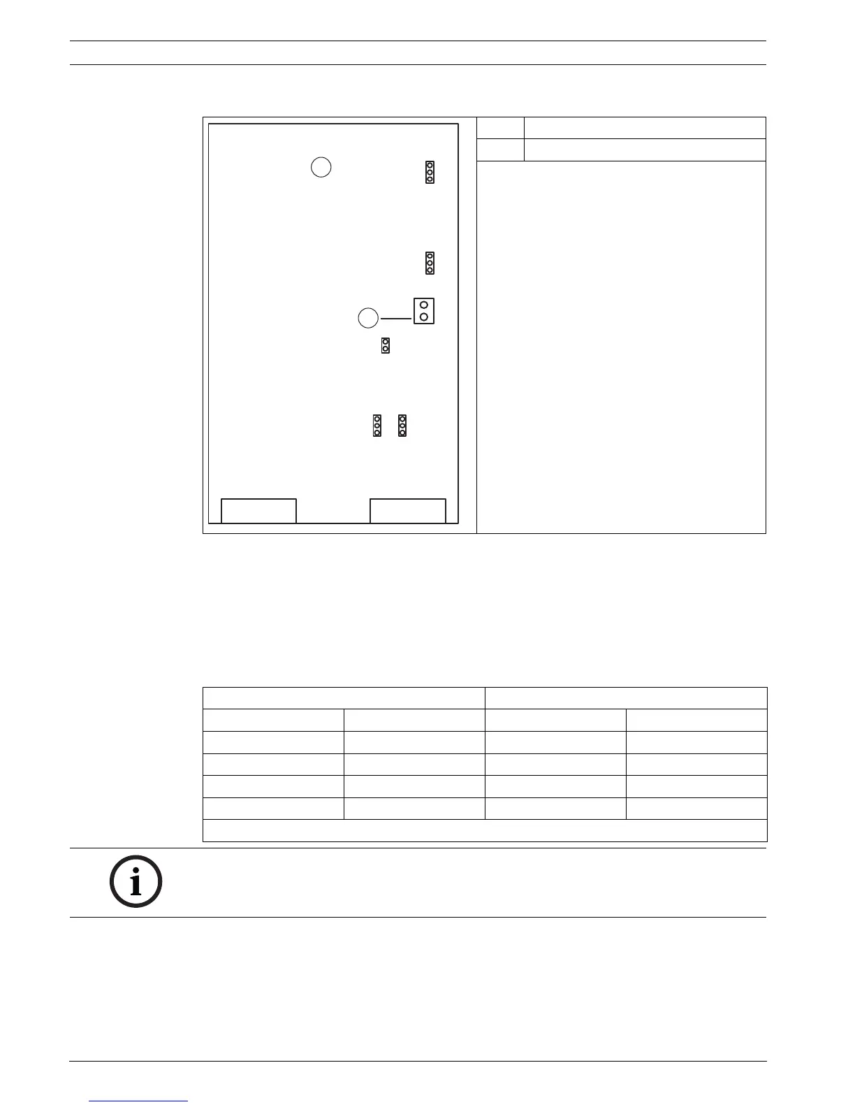
OVS interface converter bridge assignment
Exchanging transmit and receive lines
– Variant 1:
BR1, BR2: Position 1/2
ST3: Pin 2 = transmit line, Pin 3 = receive line
– Variant 2:
BR1, BR2: Position 2/3
ST3: Pin 2 = receive line, Pin 3 = transmit line
1OVS
2 12V/24V connection
Warning:
Disconnect the mains plug before opening the
OVS!
For 12 V/24 V supply
BR4: Position 1/2
BR5: Position 1/2
BR6: Position 1/2
For 230 V supply
BR4: Position 2/3
BR5: Position 2/3
BR6: Open
OPTO pin assignment V.24 (ST3) pin assignment
Direction Connection Direction Connection
Input - 1 Transmit/Receive * 2
Input + 6 Receive/Transmit * 3
Output + 5 0 V 5
Output - 9
* depending on BR1/BR2
NOTICE!
For cabling, telephone cables of type J-Y(St)Y 2x2x0.6 are recommended. The cable shielding
must be grounded at the alarm panel side to avoid earth currents.
 Loading...