26 en | Device Connections DiBos/DiBos Micro
F.01U.033.308 | V7 | 2009.09 Installation Guide Bosch Sicherheitssysteme GmbH
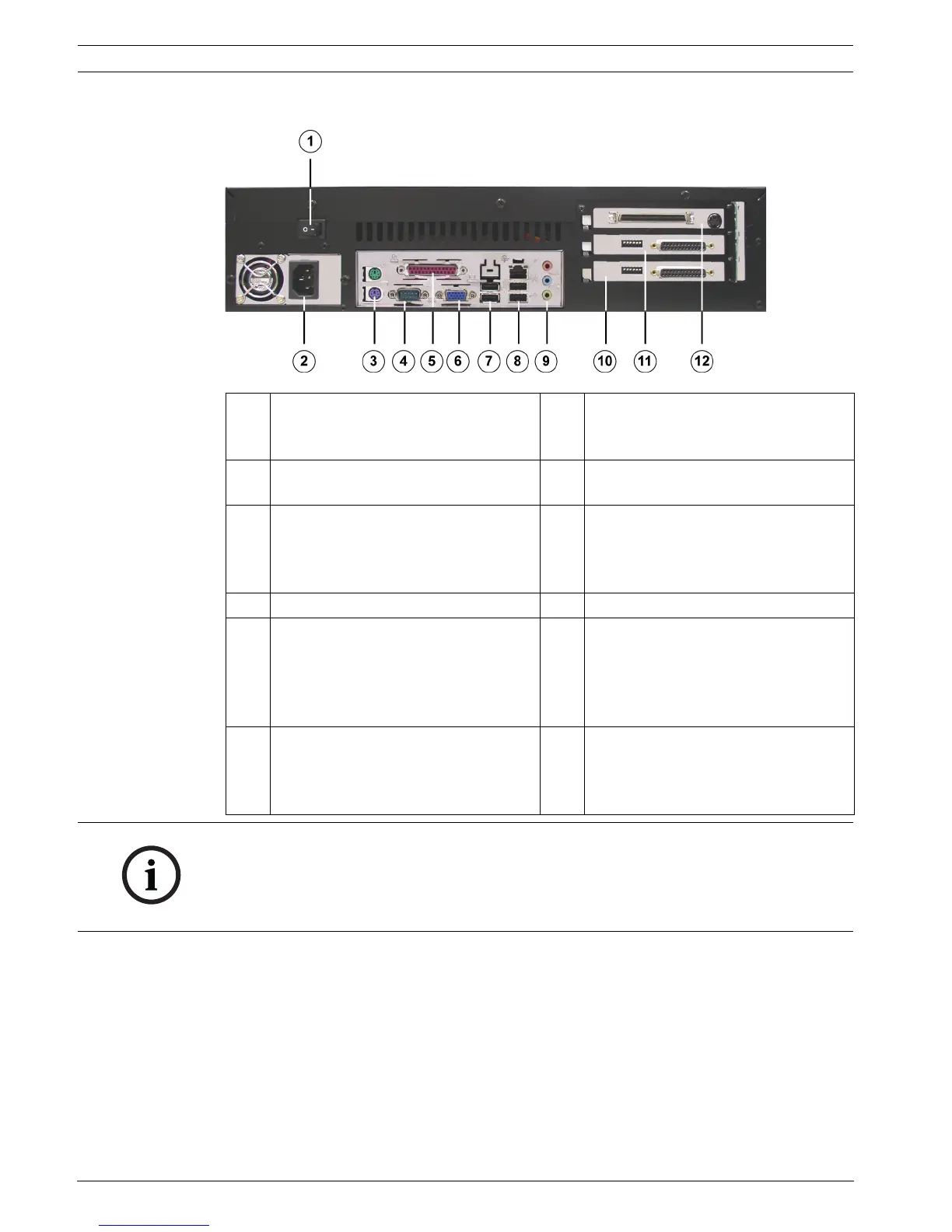
3.2.2 DiBos micro Rear View
1 On/Off switch 7 2x USB 2.0
(e.g. for mouse and keyboard with
USB connection)
2 Mains connection 100 / 240 VAC, 50 /
60 Hz (automatic switchover)
8 1x Ethernet (RJ45) - 2x USB 2.0
3 Mouse (green) - Keyboard (purple).
These connections should be used if
the mouse and keyboard are not
connected via USB.
9 Line in (blue)
Speaker out (green)
Microphone in (red), mono
4 Serial interface COM1 10 Grabber 2 (camera 7 - 12)
5 Parallel interface.
Note:
The HW dongle must be connected if
handling a device that has been
supplied with a HW dongle.
11 Grabber 1 (camera 1 - 6)
6 VGA monitor 12 I/O card with plug for connecting the
alarm inputs and relay outputs and
socket for video monitor A and video
monitor B
NOTICE!
Ferrites must be fitted to the following cables:
– Network cable (2 ferrites directly next to each other)
–Keyboard (1 ferrite)
The ferrites must to be fitted to the cable directly next to the connections.