22 en | Device Connections DiBos/DiBos Micro
F.01U.033.308 | V7 | 2009.09 Installation Guide Bosch Sicherheitssysteme GmbH
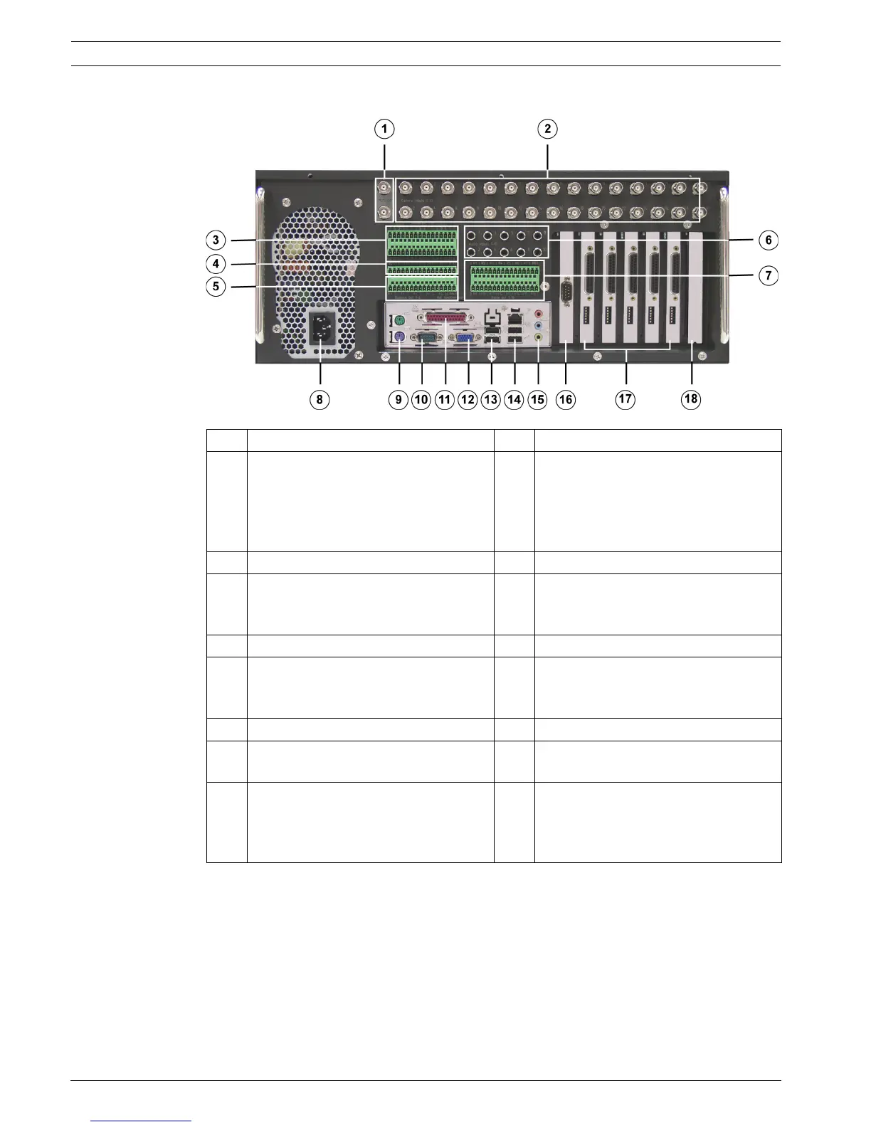
3.1.2 DiBos Rear View
1 Video monitor A/Video monitor B 10 Serial interface COM1
2 Video inputs 1 - 30 11 Parallel interface.
Note:
The HW dongle must be connected if
handling a device that has been
supplied with a HW dongle.
3 Alarm inputs 1 - 21 12 VGA monitor
4 Alarm inputs 22 - 32 13 2x USB 2.0
(e.g. for mouse and keyboard with
USB connection)
5 Biphase 1 - 4, malfunction outputs 1 14 1x Ethernet (RJ45) - 2x USB 2.0
6 Audio inputs 1 - 10 15 Line in (blue)
Speaker out (green)
Microphone in (red), mono
7 Relay outputs 1 - 16 16 Second serial interface (COM2)
8 Mains connection 100/240 VAC, 50/
60 Hz (automatic switchover)
17 Grabbers 1 - 5
9 Mouse (green) - Keyboard (purple).
These connections should be used if
the mouse and keyboard are not
connected via USB.
18 Free for optional PCI plug-in cards