28 en | Device Connections DiBos/DiBos Micro
F.01U.033.308 | V7 | 2009.09 Installation Guide Bosch Sicherheitssysteme GmbH
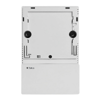
3.2.4 I/O Card (for DiBos micro)
The following can be set for the I/O card:
– the relay outputs (NO = normally open, NC = normally closed)
– the malfunction outputs (NO = normally open, NC = normally closed)
The I/O card must be removed to change the bridge settings.
1 Cable for monitor output A and monitor output B (the cables are numbered).
Cable number 1 = Monitor A
Cable number 2 = Monitor B
2 Connecting cable for 12 alarm inputs, 12 relay outputs, 3 biphase and 1 malfunction
output (for assignment, see table below)
3 16 relay outputs:
The setting is printed on the PCB.
Relay outputs 1–8: open (NO = normally open)
Relay outputs 9–16: closed (NC = normally closed)
4 Malfunction output: The setting is printed on the PCB.
Top bridge position: Open (MAL NO = malfunction normally
open)
Bottom bridge position (position when delivered): Closed (MAL
NC = malfunction normally closed)