DiBos/DiBos Micro Device Connections | en 27
Bosch Sicherheitssysteme GmbH Installation Guide F.01U.033.308 | V7 | 2009.09
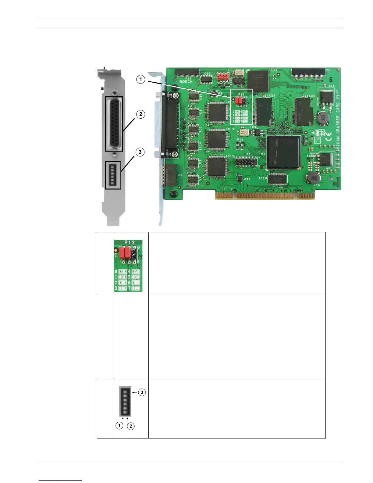
3.2.3 Grabber Card for DiBos micro
When a grabber card is retrofitted, the grabber identification (grabber 1, grabber 2 etc.) must
be set.
1 Grabber identification:
The setting for grabber card 1 and grabber card 2 is printed on
the PCB.
0 = Grabber 1
1 = Grabber 2
2 Plug for connecting cable with 6 video and 2 audio inputs (the
cables are numbered).
BNC cable number 1 (brown) = Video input 1
BNC cable number 2 (yellow) = Video input 2
BNC cable number 3 (green) = Video input 3
BNC cable number 4 (black) = Video input 4
BNC cable number 5 (white) = Video input 5
BNC cable number 6 (blue) = Video input 6
Audio cable number 1 (gray) = Audio input 1
Audio cable number 2 (red) = Audio input 2
3 Terminating video inputs:
1 = Switch position left: input terminated (position when
delivered)
2 = Switch position right: open, not terminated
3 = Topmost switch: for camera input 1 etc.
Note:
The positions relate to the illustration above.