If multiple codepads reside on the same system, each codepad must have a unique address.
The Solution 2000/3000 control panels support up to 4 codepads, addresses 01-04. DIP
switch address settings greater than 4 prevent the codepad from processing messages
received on the SDI2 bus and the option bus. Any change to the DIP switch requires a power
cycle or software reboot of the module for the new external address to be read.
DIP Switch Codepad
Address
DIP Switch Number
1 2 3 4 5 6
1 On Off Off Off Off On
2 Off On Off Off Off On
3 On On Off Off Off On
4 Off Off On Off Off On
Table 4.1: Codepad DIP switch address settings
Install the module
1. Use the provided anchors and screws to mount the codepad base on the wall.
2. Pull the necessary wiring through the mounting plate.
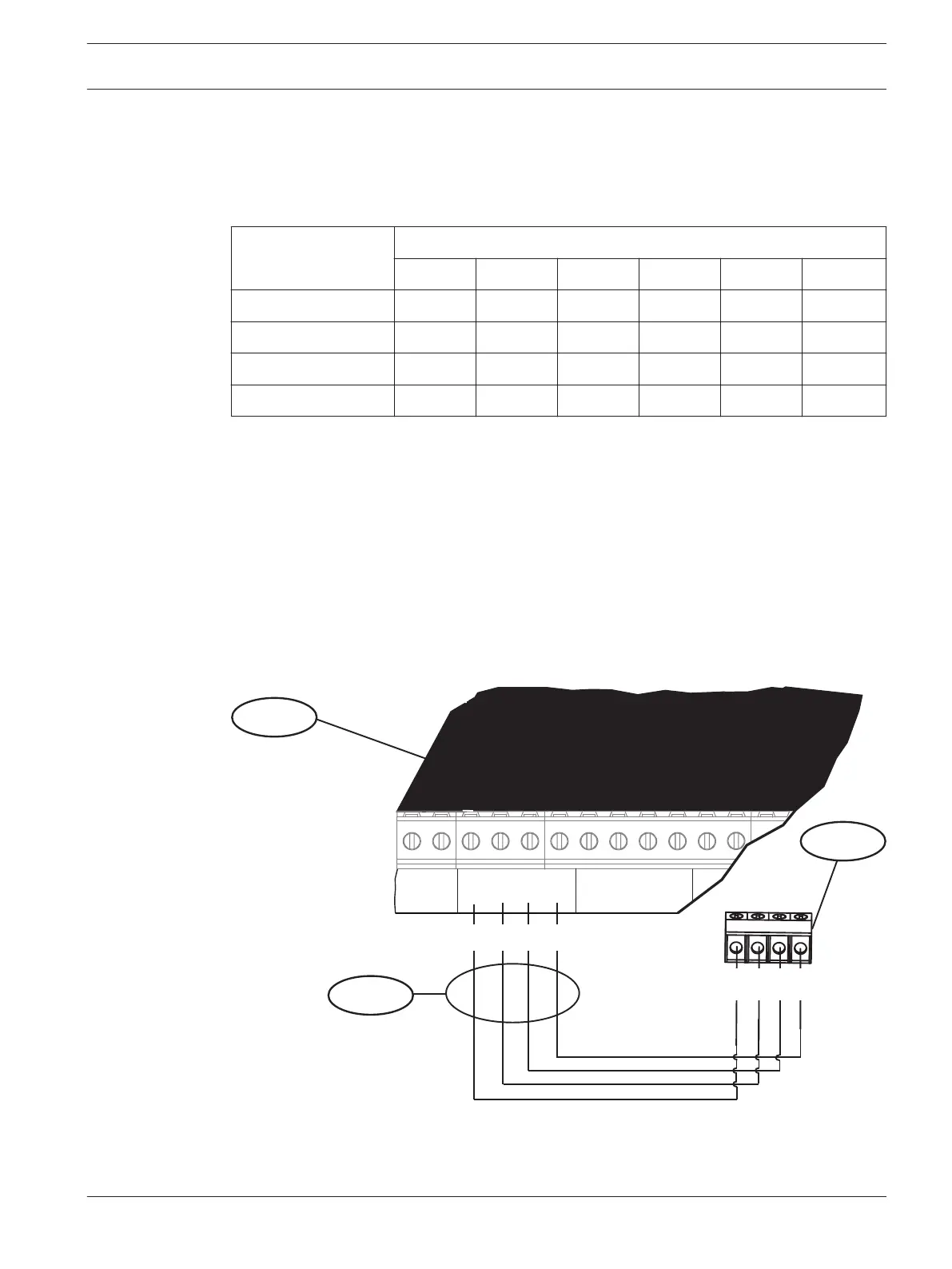
Wire to the control panel
Wire the codepad to the control panel using the control panel terminals labeled R, Y, G, B
(PWR, A, B, COM). Connect them to the codepad terminals labeled R, Y, G, B. Connect
codepads to the SDI2 data bus by parallel wire run from the control panel to each codepad,
wire from codepad to codepad, or a combination of the two. Use a maximum of 7500 ft (2286
m) of 22 AWG (0.8 mm) wire for all devices connected to the SDI2 bus combined.
1
2
3
R Y G B
1
+ -
BATTERY
PWR A B COM
R Y G B
PWR A B COM
PWR A B COM
Control Panel
Accessories | en 15
Bosch Security Systems, Inc. Installation Guide 2017.10 | 03 | F.01U.298.026