Configuration
For most installations, the default B450 settings allow installation with no device programming
required. For customized network settings, the B450 supports a USB configuration menu, or
configuration via SMS.
When the B450 is running in version 3 compatibility mode, it reports its module type as a
B426. Networking parameters can be configured using A-Link. When the cellular specific
parameters need to be modified, use USB or SMS to configure the module directly.
When the B450 is running in version 4 compatibility mode, it reports its own product type.
Both networking parameters and cellular specific parameters can be configured using A-Link.
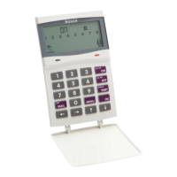
LEDs
Three LEDs provide status and troubleshooting information about the module and its
connection.
LED
Description
Heartbeat Indicates the system status of the B450 and its connection to the
control panel.
RX Indicates when an inbound packet is received on the bus.
TX Indicates when an outbound packet is transmitted on the bus.
Mounting considerations
Install in a location with acceptable wireless network signal strength. Mount the module into
the interior of a compatible enclosure. Use the 3-hole mounting pattern. Use the supplied
mounting screws.
Wiring considerations
The B450 connects to a control panel using a data bus connection via the module’s terminal
strip, or the module’s interconnect wiring connectors.
For data bus powered installations outside the compatible control panel enclosure, follow the
maximum wiring distances in the technical specifications. For further installations power from
a compatible auxiliary power supply.
A-Link Plus Software
You can program or control the Solution 2000/3000 control panels remotely using A-Link plus
Software. This software allows you to change your customer’s control panel without leaving
your office, which improves customer service and saves your time and money. For locations
where a control panel is installed hundreds of kilometers from your office, the Upload/
Download feature is invaluable.
A-Link plus software running in windows 7 OS: When selecting the control panel type during
the setup of a new customer database in the A-Link plus Software. The software version is
v4.7 or later and the control panel type is Solution 2000 or Solution 3000.
When you add a new customer in the A-Link plus Software, the “Installer code” and the “A-
Link Plus / RSC password” must match the values programmed in the control panel for
synchronization during connection to the control panel. If this location does not match those
of the control panel, the software and the control panel cannot be synchronized.
Minimum System Requirements
4.11
22 en | Accessories Control Panel
2017.10 | 03 | F.01U.298.026 Installation Guide Bosch Security Systems, Inc.