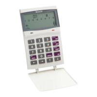
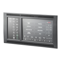
To enter Fault Analysis Mode to determine a system fault other than the AC MAINS supply:
1. Press and hold [5] until two beeps sound. The FAULT indicator remains lit and the STAY
and AWAY indicators flash. The lit zone indicators indicate the type of fault that occurred.
2. If necessary, press the button corresponding to the indicator to further determine the
fault. (Refer to the table Fault Analysis Conditions below.)
3. To exit from Fault Analysis Mode, press [AWAY]. The STAY and AWAY indicators are
extinguished and the FAULT indicator remains lit.
Fault Indicators
Zone
Indicator
Fault Description Press
Button
Zone
Indicator
Fault Condition
1 System Fault 1 1
2
3
4
5
7
8
9 to 16
Battery Fail
Date and Time
RF Receiver Fail
Output 1 to 3 Fail
Telephone Line Fail
Power Supply Fail
Onboard Tamper
RF Repeaters 1 to 8 Fail (Solution
2000 N.A.)
2 RF Low Battery
(Solution 2000
N.A.)
2 1 to 16 Zones 1 to 16 RF Low Battery
3 Zone Tamper Alarm 3 1 to 16 Zones 1 to 16 Tamper Alarm
4 Sensor Watch Fault 4 1 to 16 Zones 1 to 16 Sensor Watch Fail
5 RF Sensor Missing
(Solution 2000
N.A.)
5 1 to 16 Zones 1 to 16 RF Sensor Watch Fail
6 Communication Fail 6 1
2
3
4
5
6
Receiver 1 Fail
Receiver 2 Fail
Receiver 3 Fail
Receiver 4 Fail
IP Module 1 Fail
IP Module 2 Fail
7 Output and
Codepad Fail
7 1 to 2
3 to 6
Output Expanders 1 to 2 Fail
Codepads 1 to 4 Fail
8 Keyfob Low Battery 8 1 to 16 Keyfobs 1 to 16 Low Battery
Table 6.1: Fault Indicators
When working with a text codepad, press [5] to enter [Fault Analysis], you can page up or
page down to view the fault items, and press [AWAY] to exit from Fault Analysis Mode.
Fault descriptions
1 – System Fault
The system FAULT indicator lights when any of the faults listed in the table System FAULT
Indicators below occurs. In Fault Analysis Mode, press [1] to determine the fault that
occurred.
6.13
Control Panel System Operations | en 37
Bosch Security Systems, Inc. Installation Guide 2017.10 | 03 | F.01U.298.026
 Loading...


